Set safety enable circuitry – Rockwell Automation 21G PowerFlex 750-Series AC Drives Reference Manual User Manual
Page 30
30
Rockwell Automation Publication 750-RM001F-EN-P - February 2012
Chapter 3
Installation and Wiring
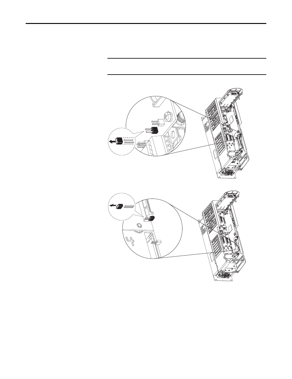
Set Safety Enable Circuitry
The PowerFlex 750-Series drive ships with the safety-enable jumper (SAFETY)
installed. The jumper, located on the main control board, must be removed when
using the Safe Speed Monitor Option module.
Figure 2 - PowerFlex 753 - SAFETY Jumper Location
Figure 3 - PowerFlex 755 - SAFETY Jumper Location (Frames 1…7 Only)
Note: Frame 8 drives do not have a safety enable jumper.
IMPORTANT
Failure to remove the SAFETY jumper will cause the drive to
fault when a start command is issued.
TIP
The Di0 digital output on the main control board can be designated as a
“hardware enable” function by removing the ENABLE jumper. If this jumper is
removed, the drive will not run unless the Di0 digital input is activated. The Di0
input is not related to the operation of the safety option. If you are not using
the Di0 input as a ‘hardware enable’ do not remove the ENABLE jumper.