Rockwell Automation 21G PowerFlex 750-Series AC Drives Reference Manual User Manual
Page 106
106
Rockwell Automation Publication 750-RM001F-EN-P - February 2012
Chapter 8
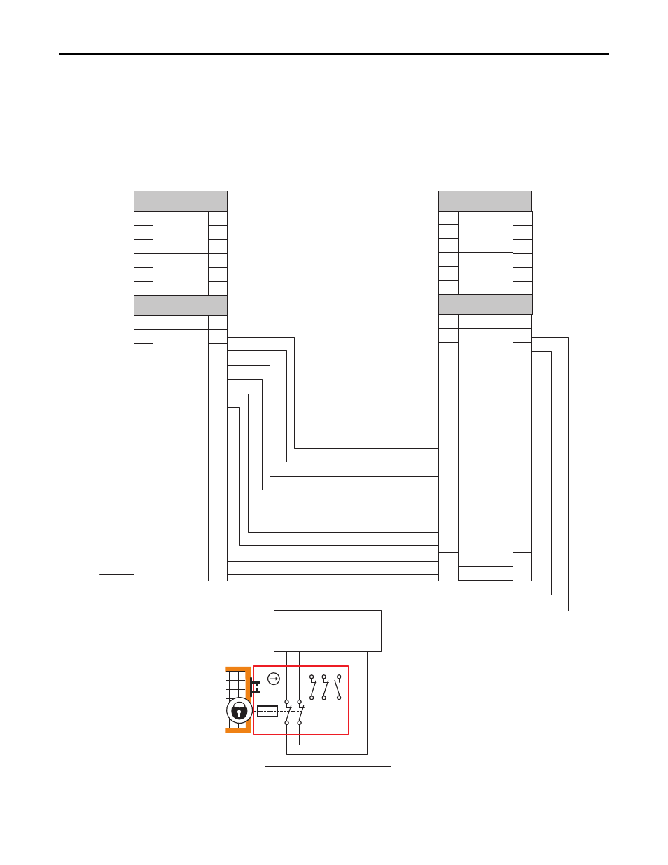
Slave Modes for Multi-axis Cascaded Systems
This second example is configured as a cascaded last unit via the P20 [Cascaded
Config] parameter (Multi Last). It has SS_In, SLS_In, and DM_In input
connections from the previous upstream safety option, but its DC_Out output is
connected to a guardlocking interlock switch.
Figure 34 - Slave, Safe Limited Speed, Last Unit
12 22 34
11 21 33
A1
A2
42
41
52
51
TB1
S11 S21
TB2
X42 X32
GND
S11
S11
S11
S21
S21
S21
TEST_OUT_0
TEST_OUT_1
+24V DC
TB1
TB2
S11
S11
S11
S21
S21
S21
A1
S12
S22
S72
S82
S52
S62
S32
S42
X32
X42
34
44
68
78
51
52
S34
A2
+24V
24V_COM
SS_IN_CHx
ESM_IN_CHx
SLS_IN_CHx
DM_IN_CHx
LM_IN_CHx
SS_OUT_CHx
SLS_OUT_CHx
DC_OUT_CHx
RESET_IN
A1
S12
S22
S72
S82
S52
S62
S32
S42
X32
X42
34
44
68
78
51
52
S34
A2
S11
S11
S11
S21
S21
S21
TEST_OUT_0
TEST_OUT_1
TB1
TB2
S11
S11
S11
S21
S21
S21
A1
S12
S22
S72
S82
S52
S62
S32
S42
X32
X42
34
44
68
78
51
52
S34
A2
+24V
24V_COM
SS_IN_CHx
ESM_IN_CHx
SLS_IN_CHx
DM_IN_CHx
LM_IN_CHx
SS_OUT_CHx
SLS_OUT_CHx
DC_OUT_CHx
RESET_IN
A1
S12
S22
S72
S82
S52
S62
S32
S42
X32
X42
34
44
68
78
51
52
S34
A2
Previous Upstream Axis
Safety Option Terminals
Last Axis
Safety Option Terminals
First Axis
Safety Option Terminals
Power to
Release
TLS3 GD2
440G-T27260