Rockwell Automation 21G PowerFlex 750-Series AC Drives Reference Manual User Manual
Page 37
Rockwell Automation Publication 750-RM001F-EN-P - February 2012
37
Speed Monitoring I/O Signals
Chapter 4
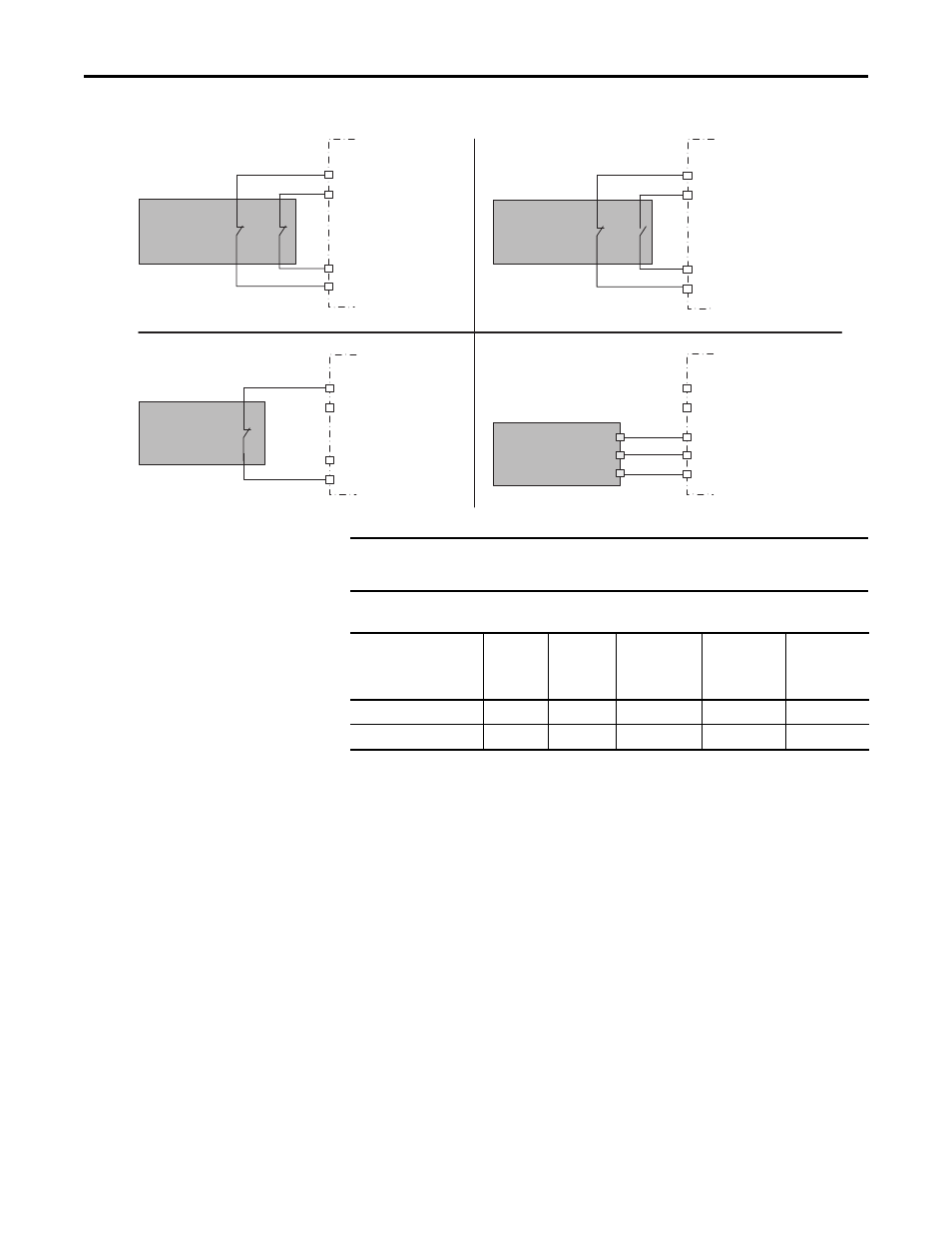
Figure 5 - Safety Input Wiring Examples
Table 4 - Safety Option Input Terminals
Short-circuits of the input loop to ground or 24V will be detected. For dual-
channel inputs, cross loops will also be detected.
Test_Out_0 (S11)
Test_Out_1 (S21)
Dual-channel
Equivalent
Safety Device
Dual-channel
Complementary
Safety Device
Single
Channel
Safety Device
Solid State
Safety Device
Safety Option
N/C
N/C
Input 1
Input 0
GND
OSSD2
OSSD1
Safety Option
Safety Option
Safety Option
Input 1
Input 0
Input 1
Input 0
24V_COM (A2)
Input 1
Input 0
Test_Out_0 (S11)
Test_Out_1 (S21)
Test_Out_0 (S11)
Test_Out_1 (S21)
Test_Out_0 (S11)
Test_Out_1 (S21)
2NC or 2 NC 3s
1NC
1NC+1NO or 1NC+1NO 3s
2 OSSD 3s
IMPORTANT
Cross wiring of Test Outputs to Inputs is not allowed. For example, do not
connect TEST_OUT_0 to Input 1 or TEST_OUT_1 to Input 0.
Function
Safe Stop
(SS_In)
Safe
Limited
Speed
(SLS_In)
Door
Monitoring
(DM_In)
Enabling
Switch
Monitoring
(ESM_In)
Lock
Monitoring
(LM_In)
Input 0 = Channel 0
S12
S52
S32
S72
X32
Input 1 = Channel 1
S22
S62
S42
S82
X42