Example 2: max speed group – Rockwell Automation 21G PowerFlex 750-Series AC Drives Reference Manual User Manual
Page 149
Rockwell Automation Publication 750-RM001F-EN-P - February 2012
149
Configuration Examples
Chapter 11
5. Choose the P59 [Lock Mon Enable] parameter.
The default value is 0 (Disabled) for applications without an interlock
switch.
6. Set the P59 [Lock Mon Enable] parameter value to 1 (Enabled) because
this application uses the TLS-3 GD2 interlock switch.
7. Choose the P60 [Lock Mon Input] parameter.
The default value is 0 (Not Used) for applications that do not use an
interlock switch.
8. Set the P60 [Lock Mon Input] parameter value to 1 for 2NC (dual-
channel equivalent) operation.
In this example application, the Lock Monitor Input (LM_In) monitors
the TLS-3 GD2 switch, which has two normally-closed (2NC) interlock
monitoring contacts.
9. Go to the next section to set the parameters that configure Safe Maximum
Speed monitoring.
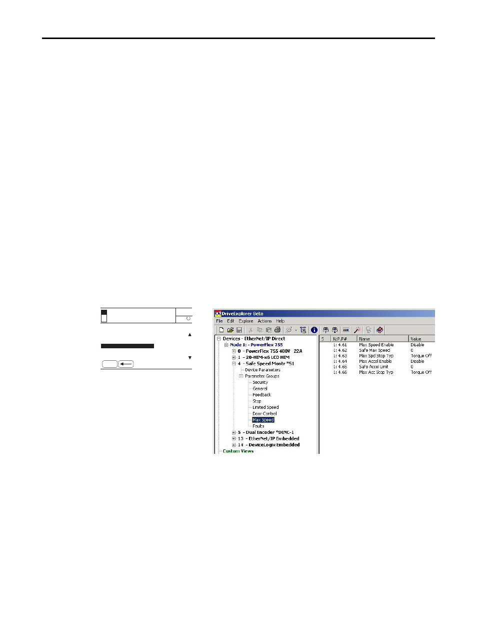
Example 2: Max Speed Group
Figure 59 - Max Speed Group Parameters
Follow these steps to configure Maximum Speed monitoring for the safety
option.
1. From the Max Speed group, choose the P61 [Max Speed Enable]
parameter.
The default value is 0 (Disabled) for no maximum speed limitation.
2. Set the P61 [Max Speed Enable] parameter value to 1 (Enabled), which
monitors that the encoder feedback signal does not exceed the velocity
configured by using the Safe Max Speed parameter.
Port 04: Param File-Group
FILE: Parameter Groups
Max Speed Enable
ESC
AUTO
Not Enabled
0.000 Hz
F
GROUP: Max Speed
Safe Max Speed
Max Spd Stop Typ
HIM Screen
Software Screen