Rockwell Automation 21G PowerFlex 750-Series AC Drives Reference Manual User Manual
Page 90
90
Rockwell Automation Publication 750-RM001F-EN-P - February 2012
Chapter 7
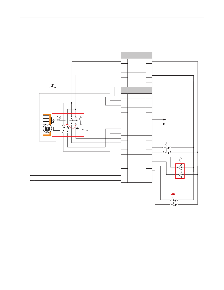
Safe Limited Speed (SLS) Modes
SLS with Door Monitoring
and Enabling Switch
Monitoring Wiring Example
This example illustrates wiring for SLS with door monitoring and enabling
switch monitoring.
Figure 24 - Master, Safe Limited Speed with Door Monitoring and Enabling Switch Monitoring
(First or Single Unit)
(1) Lock monitoring connections are not required for Safe Limited Speed with Door Monitoring and Enabling Switch Monitoring mode
operation.
GND
S11
S11
S11
S21
S21
S21
TEST_OUT_0
TEST_OUT_1
+24V DC
TB1
TB2
S11
S11
S11
S21
S21
S21
A1
S12
S22
S72
S82
S52
S62
S32
S42
X32
X42
34
44
68
78
51
52
S34
A2
+24V
24V_COM
SS_IN_CHx
ESM_IN_CHx
SLS_IN_CHx
DM_IN_CHx
LM_IN_CHx
SS_OUT_CHx
SLS_OUT_CHx
DC_OUT_CHx
RESET_IN
A1
S12
S22
S72
S82
S52
S62
S32
S42
X32
X42
34
44
68
78
51
52
S34
A2
12 22 34
11 21 33
A1
A2
42
41
52
51
(1)
1
2
3
4
PowerFlex 750-Series
Safe Speed Monitor
Option Module
SLS
Request
SS
Request
Reset
Safety Stop
to Next Axis
(optional)
Remove (2)
Internal
Jumpers
Power to
Release
440J-N21TNPM
Enabling Switch
TLS3 GD2
440G-T27260
Safety Switch