Outputs, Safe stop output (ss_out) – Rockwell Automation 21G PowerFlex 750-Series AC Drives Reference Manual User Manual
Page 41
Rockwell Automation Publication 750-RM001F-EN-P - February 2012
41
Speed Monitoring I/O Signals
Chapter 4
Outputs
The safety option has three safety control outputs. The outputs have various
output current capabilities, depending on function.
See the specifications in
to verify your power requirements.
Safe Stop Output (SS_Out)
The safe state for this signal is OFF.
These outputs are typically used in multi-axis applications. In multi-axis
applications, you can use these outputs to daisy-chain the master safety option to
a slave.
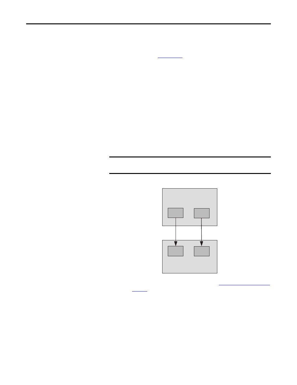
For SS_Out to SS_In cascaded signals, the interface is a dual-channel sourcing
solid-state safety output connected to a dual-channel safety input configured as
OSSD. The outputs are pulse-tested when the P72 [SS Out Mode] parameter is
configured for pulse-testing.
Figure 6 - SS_Out to SS_In Connections for Multi-axis Applications
For more information on multi-axis configurations, see
starting on
.
Alternately, the first SS_Out output may be used to signal a programmable logic
controller (PLC) that a Safe Stop has been requested.
If the SS_In is ON (closed) and a successful Safe Stop Reset is performed, the
SS_Out output is turned ON. If Lock Monitoring is not enabled or the door
control logic state is Unlock, the SS_Out signal turns ON immediately when the
SS_In turns ON. If Lock Monitoring is enabled, and the door control logic state
is Lock, the SS_Out signal is not turned ON until the door has been locked by
using the DC_Out signal and the LM_In input has been verified as ON.
IMPORTANT
If you disable pulse-testing on this output, the achievable SIL, Category, and PL
ratings of your entire safety system are reduced.
Safety Option (Master)
SS_OUT_CH0
SS_OUT_CH1
Safety Option (Slave)
SS_IN_CH0
SS_IN_CH1
TB2-S12 and TB2-S22 are
configured as 2 OSSD 3s inputs.
TB2-34
TB2-S12
TB2-44
TB2-S22