Install the powerflex safety option module – Rockwell Automation 21G PowerFlex 750-Series AC Drives Reference Manual User Manual
Page 31
Rockwell Automation Publication 750-RM001F-EN-P - February 2012
31
Installation and Wiring
Chapter 3
Install the PowerFlex Safety
Option Module
There are multiple option module port positions in PowerFlex 750-Series drives.
Restrictions and/or recommendations apply to selected option modules.
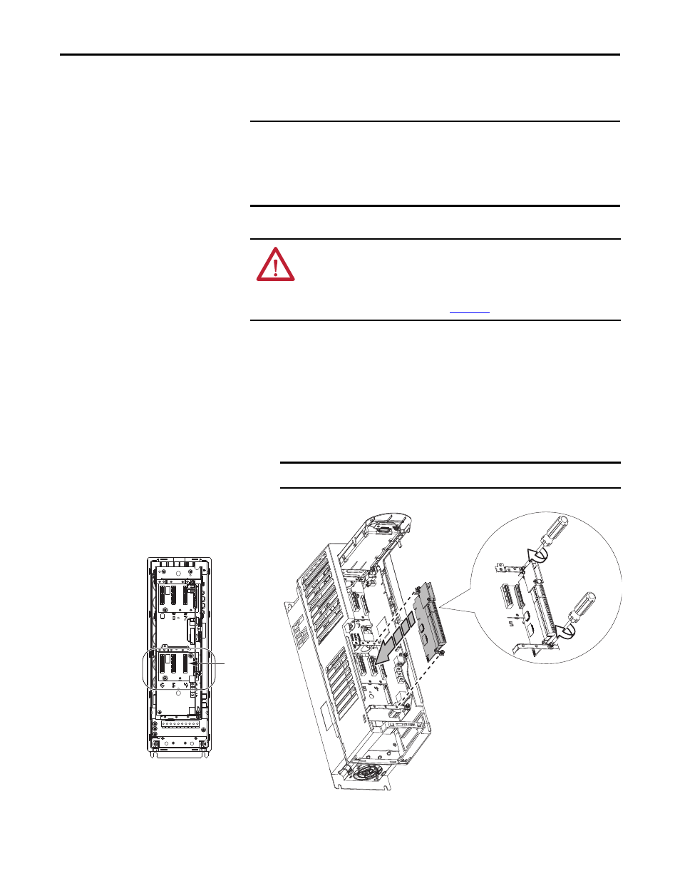
Follow these steps to install the PowerFlex safety option.
1. Firmly press the option module edge connector into the desired option
module port.
2. Tighten the top and bottom retaining screws.
– Recommended torque = 0.45 N•m (4.0 lb•in)
– Recommended screwdriver = T15 Hexalobular
IMPORTANT
The PowerFlex safety option module must be installed in port 4, 5, or 6 and
must be used with the 20-750-DENC-1 Dual Incremental Encoder module or
the 20-750-UFB-1 Universal Feedback module.
When used in an Integrated Motion application, the Safe Speed Monitor option
must be installed in port 6.
ATTENTION: Hazard of equipment damage exists if an option module is
installed or removed while the drive has power applied. To avoid damaging the
drive, verify that the voltage on the bus capacitors has discharged before
performing any work on the drive. Refer to the PowerFlex 750-Series AC Drive
Installation Instructions, publica
, for more information.
IMPORTANT
Do not over-tighten retaining screws.
PowerFlex 750-Series Drive (Frame
2 drive is shown)
Ports 4, 5, 6