Safe stop 1 and safe stop 2 – Rockwell Automation 21G PowerFlex 750-Series AC Drives Reference Manual User Manual
Page 63
Rockwell Automation Publication 750-RM001F-EN-P - February 2012
63
Safe Stop and Safe Stop with Door Monitoring Modes
Chapter 6
Safe Stop 1 and Safe Stop 2
When Safe Stop 1 or 2 is initiated by a transition of the SS_In input from ON to
OFF, the safety option does not initiate the configured Stop Delay P47 [Max
Stop Time] until after the optional Stop Monitoring Delay P46 [Stop Mon
Delay] expires, unless a Stop Category fault occurs during the Stop Monitoring
Delay.
When Safe Stop 1 or 2 is initiated by a Stop Category fault, the Stop Delay P47
[Max Stop Time] begins immediately, regardless of whether a Stop Monitoring
Delay P46 [Stop Mon Delay] is configured.
Deceleration monitoring takes place during the Stop Delay P47 [Max Stop
Time]. These three configurable parameters define the deceleration profile that is
used:
• Deceleration Reference Speed, P50 [Decel Ref Speed]
• Deceleration Tolerance, P51 [Stop Decel Tol]
• Stop Delay, P47 [Max Stop Time]
If Standstill Speed is detected any time after the Safe Stop has been initiated and
before the Stop Delay P47 [Max Stop Time] expires, door control logic is set to
Unlock. If the Standstill Speed is not detected by the end of the configured Stop
Delay P47 [Max Stop Time], a Stop Speed fault occurs. For Safe Stop 1, motion
power is removed when Standstill Speed is reached. For Safe Stop 2, motion
power is not removed.
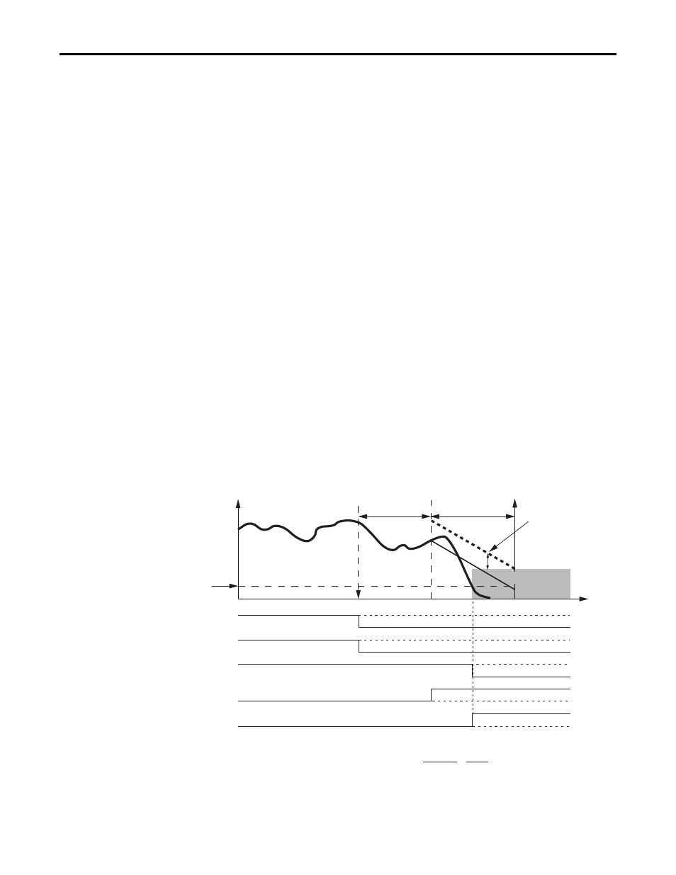
Figure 12 - Timing Diagram for Safe Stop 1
(1) This signal is internal, between the safety option and drive.
(2) DC_Out output shown configured as Power to Release. See
for more information.
Stop Request
Stop Delay: P47
Safe Torque-off
Active
P51 [Stop Decel Tol]
P48 [Standstill Speed]
Speed
Stop Monitoring Delay:
P46
SS_Out Signal
SS_In Signal
Time
Motion Power
(1)
DC_Out Output
(2)
Stop Command
(1)