Example 1: door control group settings – Rockwell Automation 21G PowerFlex 750-Series AC Drives Reference Manual User Manual
Page 138
138
Rockwell Automation Publication 750-RM001F-EN-P - February 2012
Chapter 11
Configuration Examples
Example 1: Door Control Group Settings
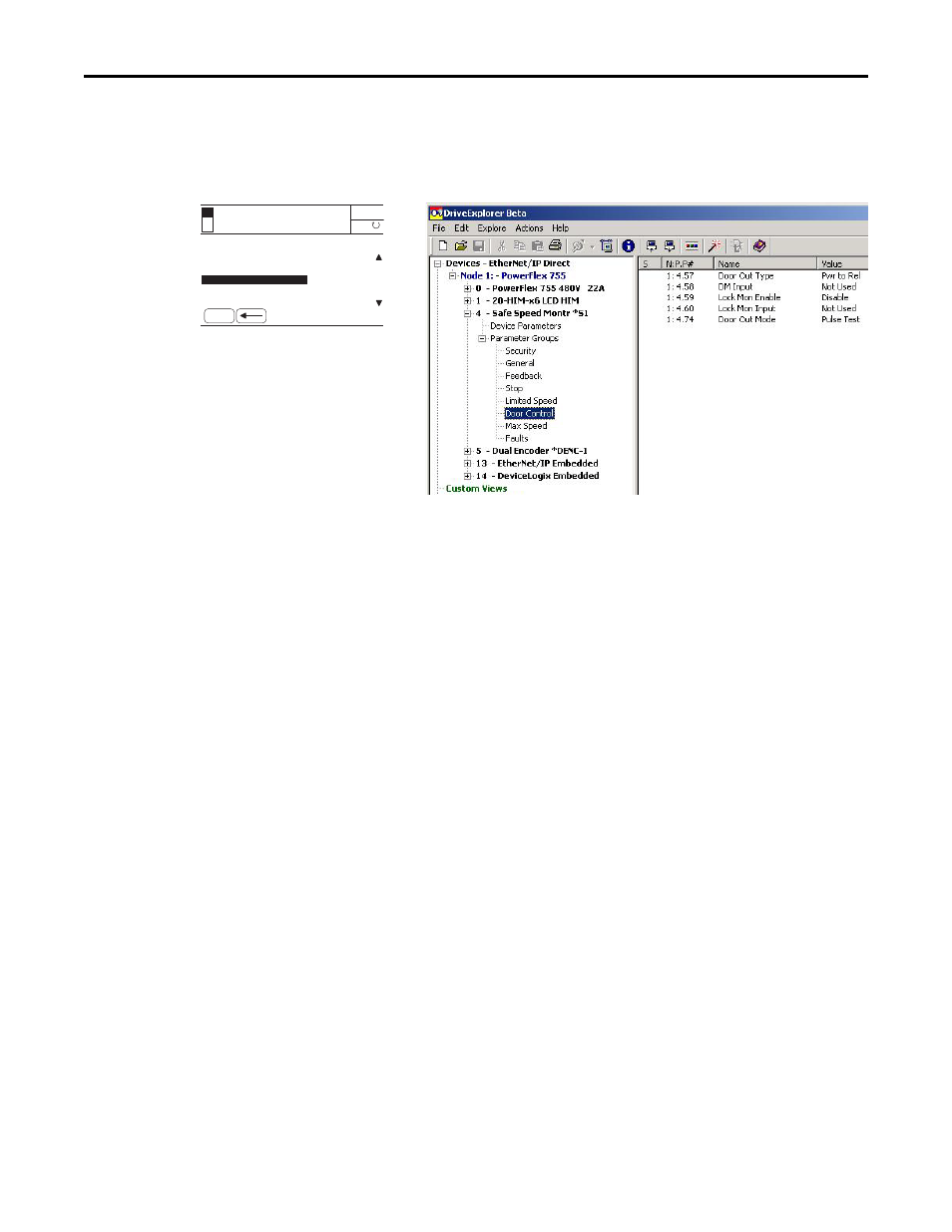
Figure 51 - Door Control Group Parameters
Follow these steps to configure Door Control operation for the safety option.
1. From the Door Control group, choose the P57 [Door Out Type]
parameter.
2. Set the P57 [Door Out Type] parameter to 0 (default), which equals
Power to Release (Pwr to Rel).
This setting was chosen because power must be applied to the solenoid
inside the TLS-3 GD2 gate switch to release the gate interlock.
3. Choose the P58 [DM Input] parameter.
The default setting is 0 for applications that do not use an interlock switch.
4. Set the P58 [DM Input] parameter value to 1 for 2NC (dual-channel
equivalent) operation.
In this example application, the DM Input (DM_In) monitors the TLS-3
GD2 switch, which has two normally-closed (2NC) safety contacts.
5. Choose the P59 [Lock Mon Enable] parameter.
The default value is 0 (Disabled) for applications without an interlock
switch.
6. Set the P59 [Lock Mon Enable] parameter value to 1 (Enabled) because
this application uses the TLS-3 GD2 interlock switch.
7. Choose the P60 [Lock Mon Input] parameter.
The default value is 0 (Not Used) for applications that do not use an
interlock switch.
Port 04: Param File-Group
FILE: Parameter Groups
Door Out Type
ESC
AUTO
Not Enabled
0.000 Hz
F
GROUP: Door Control
DM Input
Lock Mon Enable
HIM Screen
Software Screen