Scaling non-directional analog inputs, Scaling ±1ma analog inputs – SATEC PM174 Manual User Manual
Page 75
Chapter 4 PAS
Application Software
General Meter Setup
Series PM174 Powermeters
75
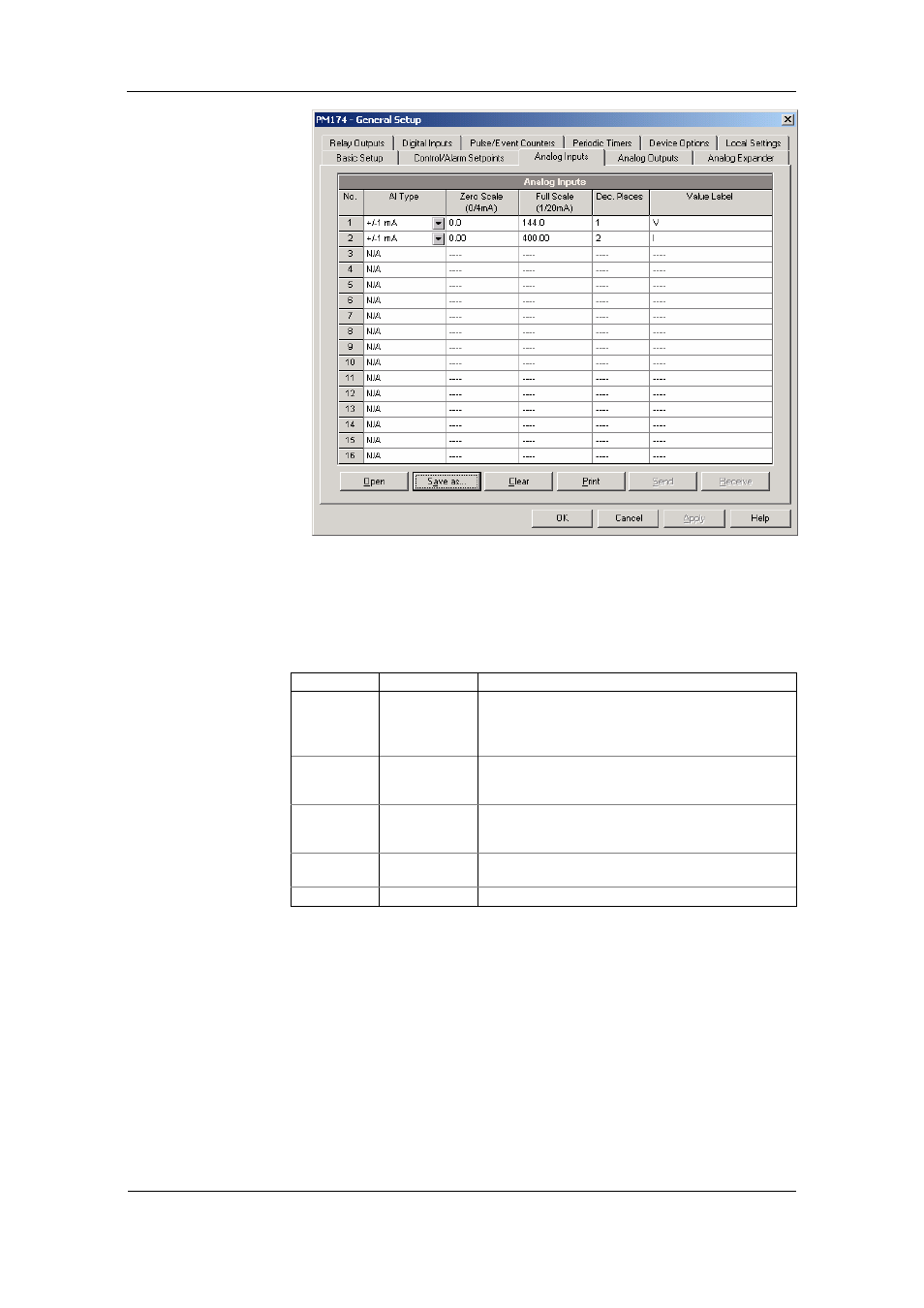
To configure the Analog Inputs in your device, select General
Setup from the Meter Setup menu, and click on the Analog
Inputs tab. If you are programming your device online, analog
inputs are designated as not available if they are not present in
the device.
The available options are described in the following table.
Option Range Description
AI type
0-1mA
±1mA
0-20mA
4-20mA
The analog input type. When connected to the meter,
shows the actual type received from the device. When
working off-line, select the analog input option
corresponding to your meter.
Zero scale
-999,999 to
999,999
Defines the low engineering scale (in primary units) for
the analog input corresponding to a lowest (zero) input
current (0 or 4 mA)
Full scale
-999,999 to
999,999
Defines the high engineering scale (in primary units) for
the analog input corresponding to a highest input
current (1 or 20 mA)
Dec. Places
0-3
The number of decimal digits in a fractional part of the
scaled engineering value
Value label
An arbitrary name you can give the analog input value
Always save your analog inputs setup to the site database in
order to keep the labels you give the analog inputs. They are
not stored in your device.
Scaling Non-directional Analog Inputs
For non-directional analog inputs with the 0-1mA, 0-20mA and
4-20mA current options, provide both zero and full engineering
scales. Each of the scales operates independently.
Scaling ±1mA Analog Inputs
For directional ±1mA analog inputs, you should provide only
the engineering scale for the +1 mA input current. The
engineering scale for the 0 mA input current is always equal to