Analog inputs setup – SATEC PM174 Manual User Manual
Page 51
Chapter 3 Display
Operations
Menu Operations
Series PM174 Powermeters
51
Label Parameter
Options
Description
On.1-On.4 Operate
limit
The threshold (in primary units) at
which the conditional expression
would be evaluated to true. Not
applicable for digital triggers.
OFF.1-
OFF.4
Release limit
The threshold (in primary units) at
which the conditional expression
would be evaluated to false. Defines
the hysteresis for analog triggers.
Not applicable for digital triggers.
Act.1-Act.4 Setpoint
action
#1-#4
See
Appendix C
The action performed when the
setpoint expression is evaluated to
true (the setpoint is in operated
state)
On d
Operate delay
0-999.9 sec The time delay before operation
when the operate conditions are
fulfilled
OFF d
Release delay
0-999.9 sec The time delay before release when
the release conditions are fulfilled
Analog Inputs Setup
This entry appears only if the meter is ordered with optional
analog inputs. For more information on configuring analog
inputs in your meter, see “Programming Analog Inputs” in
Chapter 4.
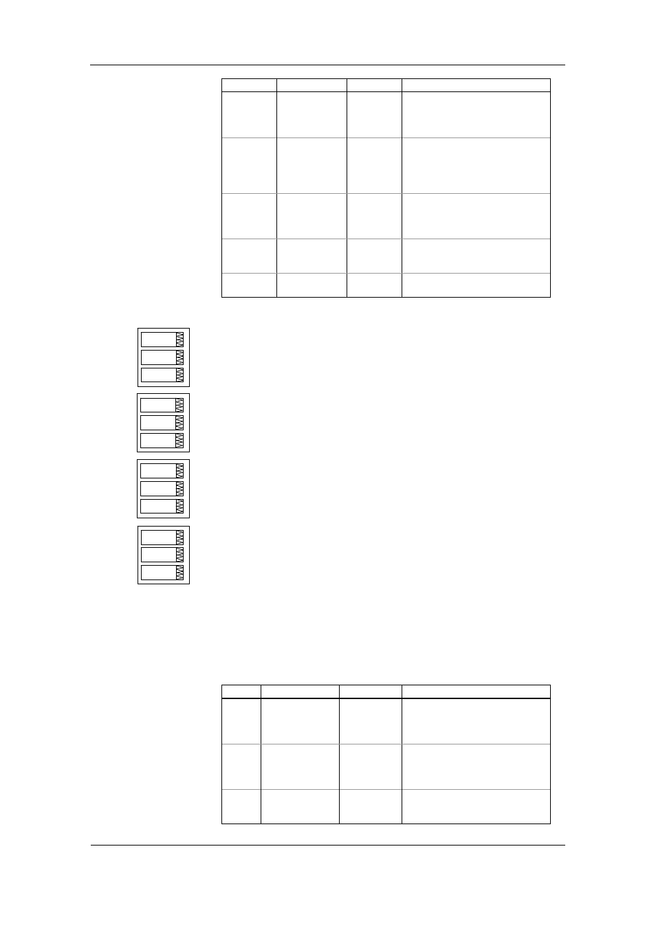
To enter the menu, select the “A.In.1” or “A.In.2” entry from the
main menu for the AI1 and AI2 input respectively, and then
press the ENTER button.
To change the analog input options:
1. Use the UP and DOWN arrow buttons to scroll to the
desired parameter.
2. Press the SELECT button to activate the lower window.
3. Use the UP and DOWN arrow buttons to adjust the
parameter value.
4. Press ENTER to confirm your new parameter setting, or
press ESC to discard changes.
5. You are returned to the middle window to select another
parameter, or store your new settings and exit the menu.
To store your new settings and exit the menu:
1. When the middle window is highlighted, press the ENTER
button.
2. You return to the main menu.
To exit the menu without saving your changes, press ESC.
The following table lists available analog input options.
Label Parameter
Options
Description
Lo Zero
scale 0-999,999
The low engineering scale (in
primary units) for the analog input
corresponding to a lowest (zero)
input current (0 or 4 mA)
Hi Full
scale
0-999,999
The high engineering scale (in
primary units) for the analog input
corresponding to a highest input
current (1 or 20 mA)
dEc.P Number
of
decimal places
0-3
The number of decimal digits in a
fractional part of the scaled
engineering value
A.In.1
ESC
A.In.1
0
Lo
A.In.1
230
Hi
A.In.1
1
dEc.P