Analog outputs setup, Analog expander setup – SATEC PM174 Manual User Manual
Page 52
Chapter 3 Display
Menu Operations
52
Series PM174 Powermeters
Analog Outputs Setup
This entry appears only if the meter is ordered with optional
analog outputs. For more information on configuring analog
inputs in your meter, see “Programming Analog Outputs” in
Chapter 4.
To enter the menu, select the “A.Ou.1” or “A.Ou.2” entry from
the main menu for the AO1 and AO2 output respectively, and
then press the ENTER button.
To change the analog output options:
1. Use the UP and DOWN arrow buttons to scroll to the
desired parameter.
2. Press the SELECT button to activate the lower window.
3. Use the UP and DOWN arrow buttons to adjust the
parameter value.
4. Press ENTER to confirm your new parameter setting, or
press ESC to discard changes.
5. You are returned to the middle window to select another
parameter, or store your new settings and exit the menu.
To store your new settings and exit the menu:
1. When the middle window is highlighted, press the ENTER
button.
2. You return to the main menu.
To exit the menu without saving your changes, press ESC.
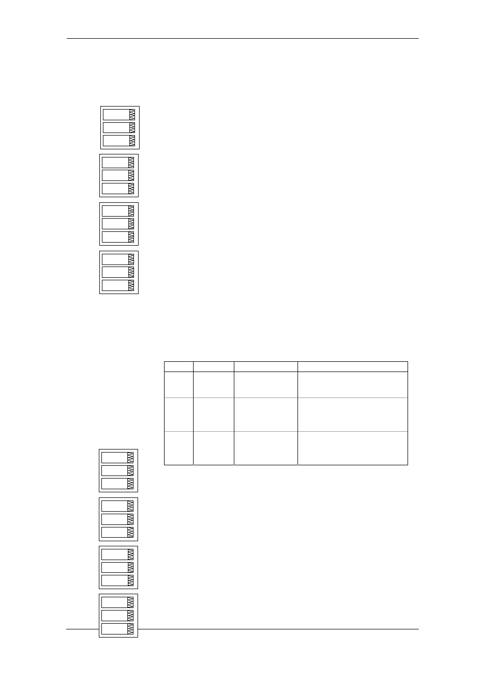
The following table lists available analog output options. For a
list of the available output parameters and their scales, see
“Programming Analog Outputs” in Chapter 4.
Label Parameter Options
Description
OutP Output
parameter
See Appendix B
Selects the measured parameter to
be transmitted through the analog
output channel.
Lo Zero
scale
Low engineering scale (in primary
units) for the analog output
corresponding to a lowest (zero)
output current (0 or 4 mA)
Hi Full
scale
High engineering scale (in primary
units) for the analog output
corresponding to a highest output
current (1 or 20 mA)
Analog Expander Setup
The meter can provide 16 additional analog outputs via two
optional AX-8 analog expanders that are connected through a
serial RS-422 interface to the meter port COM2. Each
expander has its own address 0 or 1 on the serial interface.
This menu allows you to assign parameters for the expanded
analog outputs and to specify their scales. For more
information on configuring the analog expander outputs in your
meter, see “Programming the Analog Expander” in Chapter 4.
To enter the menu, select the “AEPn” entry from the Main
menu, and press the ENTER button.
The expanded analog outputs are labeled in the following
manner: analog output channels A1-1 through A1-8 are
A.Ou.1
ESC
A.Ou.1
rt.U1
OutP
A.Ou.1
0
Lo
A.Ou.1
230
Hi
AEPn
ESC
A1-1
Ar.U1
OutP
A-1
0
Lo
A1-1
120
Hi