SATEC PM174 Manual User Manual
Page 103
Chapter 4 PAS
Application Software
Configuring Communication Protocols
Series PM174 Powermeters
103
A change event point index is normally the same as for the
corresponding static object point. If you wish to use
independent numeration for event points, enable re-mapping
event point indices via DNP Options setup (see above) so they
would start with index 0.
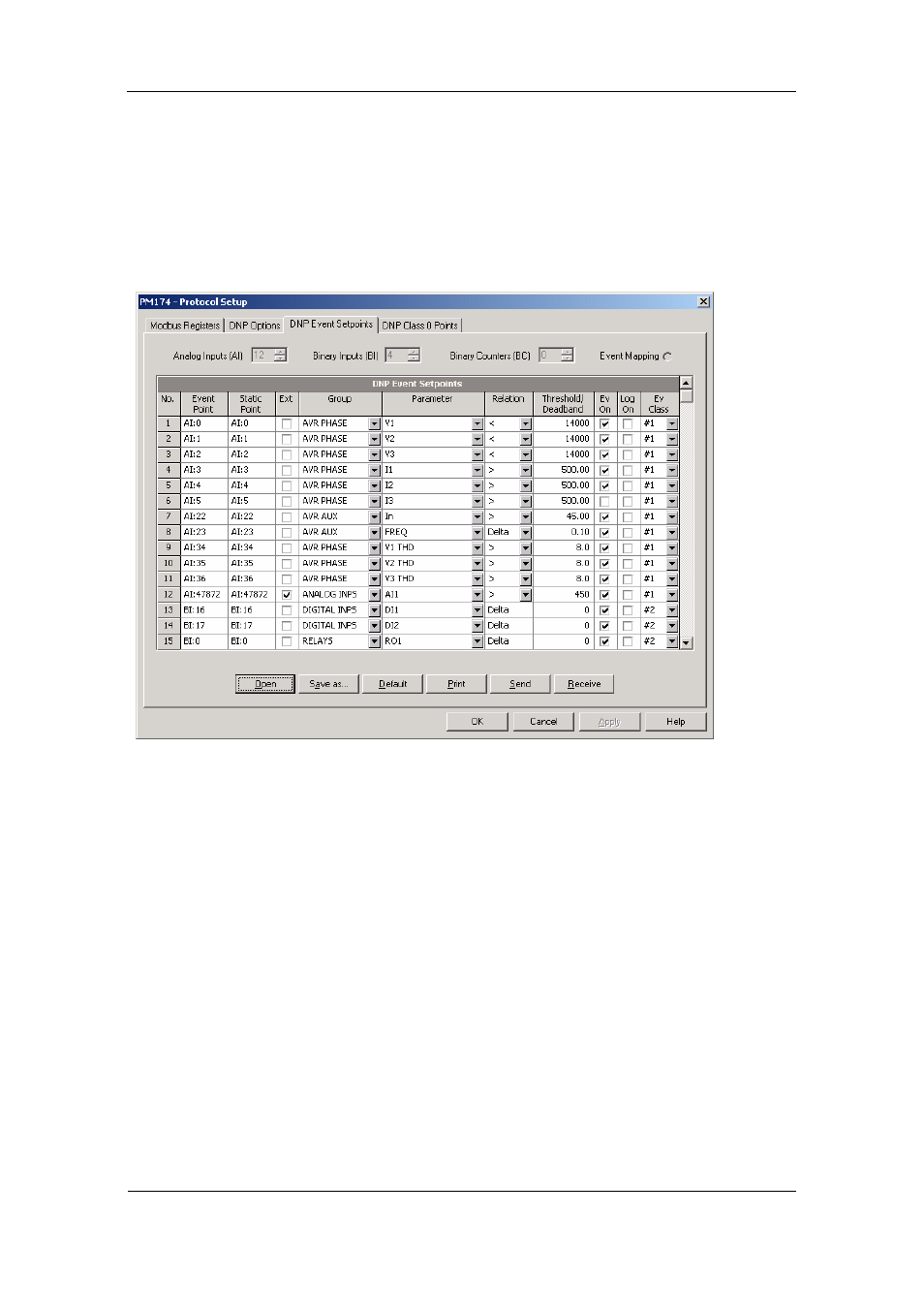
You should define a separate event setpoint for each static
object point you wish to be monitored for change events. To
view or change the factory-set DNP event setpoints, select
Protocol Setup from the Meter Setup menu and click on the
DNP Event Setpoints tab.
The number of event setpoints for each static object type is
specified via the DNP Options setup (see above). Notice that
the device clears all event buffers and links the default set of
static points to each event object type every time you change
the number of points for any of the objects.
To define setpoints for selected static points:
1. Check the “Ext” box if you wish to use the extended point
list.
2. Select a parameter group and then a desired parameter
for each event point.
3. For AI and BC points, select a relation and an operating
threshold or a deadband to be used for detecting events.
All thresholds are specified in primary units. The following
relations are available:
Delta – a new event is generated when the absolute
value of the difference between the last
reported point value and its current value
exceeds the specified deadband value;
More than (over) - a new event is generated when the
point value rises over the specified threshold,
and then when it returns below the threshold
minus a predefined return hysteresis –
applicable for AI objects;