Control setpoints setup – SATEC PM174 Manual User Manual
Page 50
Chapter 3 Display
Menu Operations
50
Series PM174 Powermeters
Control Setpoints Setup
The PM174 provides 16 control setpoints with programmable
operate and release delays. Each setpoint evaluates a logical
expression with up to four arguments using OR/AND logic.
Whenever an expression is evaluated as “true”, the setpoint
performs up to four concurrent actions that can send a
command to the output relays, increment or decrement a
counter, or trigger a recorder. For more information on
setpoints operation, see “Using Control Setpoints” in Chapter
4.
This menu configures setpoints through the front display. To
enter the menu, select the “SEtP” entry from the main menu,
and press the ENTER button.
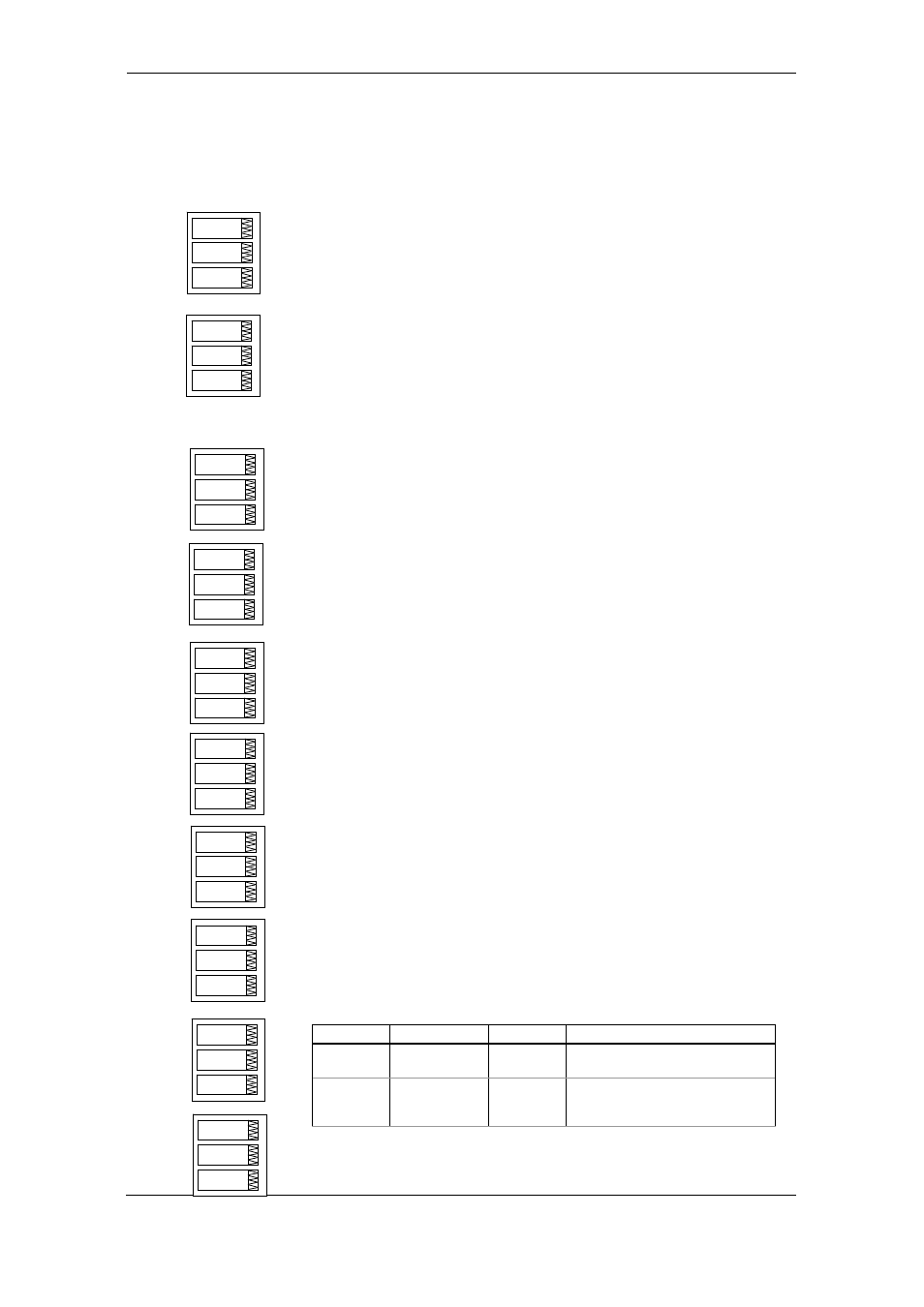
The menu uses three entries:
1. The upper window indicates a setpoint number.
2. The middle window selects a setup parameter to view or
change.
3. The lower window displays the parameter value.
Use the UP and DOWN arrow buttons to scroll to the desired
setpoint.
To select a setpoint parameter:
1. Press the SELECT button to activate the middle window.
2. Use the UP and DOWN arrow buttons to scroll to the
desired parameter.
To change the parameter value:
1. Press the SELECT button to activate the lower window.
2. Use the UP and DOWN arrow buttons to select the
desired value.
3. Press ENTER to confirm your new parameter setting, or
press ESC to discard changes.
4. You are returned to the middle window to select and
configure another parameter, or confirm the setpoint
settings and exit the menu.
To store your new setpoint settings after you configured all
setpoint parameters:
1. When the middle window is highlighted, press the ENTER
button.
2. You are returned to the upper window to select another
setpoint or exit the menu.
To exit the menu, press ESC.
The following table lists available setpoint options. For a list of
available setpoint triggers and actions, see “Using Control
Setpoints” in Chapter 4.
Label Parameter
Options
Description
LGC.2-
LGC.4
Logical operator OR, AND
Combines setpoint triggers in a
logical expression
TrG.1-TrG.4 Trigger
parameter #1-
#4
See
Appendix C
The analog or digital value that is
used as an argument in a logical
expression
SP.1
rtHi.C1
trG.1
SEtP
ESC
SP.1
200
On.1
SP.1
180
OFF.1
SP.1
Or
LOG.2
SEtP
rEL.1
Act.1
SP.1
rtHi.C2
trG.2
SP.1
200
On.2
SP.1
180
OFF.2
SEtP
ESC