4 digital output signals, 1 description, Digital output signals – Lenze LDECBBF1xxxxxxHx User Manual
Page 49: Description, Function library
Function library
Digital output signals
Description
l
49
LDEDS−CCU210B EN 4.0
8.4
Digital output signals
8.4.1
Description
The vehicle control system is equipped with digital outputs and a message bar output to
provide digital output signals.
ƒ
Basic circuit diagram: (
¶ 29)
ƒ
The internal status signals are assigned to the output signals via the assignment
logic (C0415).
Digital outputs
There are 2 digital outputs to control the actor technology at the suspension gear of the
monorail overhead conveyor.
Additionally you can logically invert each output.
Message bar
The digital output signals via the message bar serve as a feedback from the vehicle control
system to the higher−level system control.
A message bar output (MS1) is provided.
You can output the digital signals "positive half wave" and "negative half wave".
)
Note!
The reference phase in the Lenze setting is L3.
On customer request, the reference phase L1 can be supplied by adapting the
hardware.
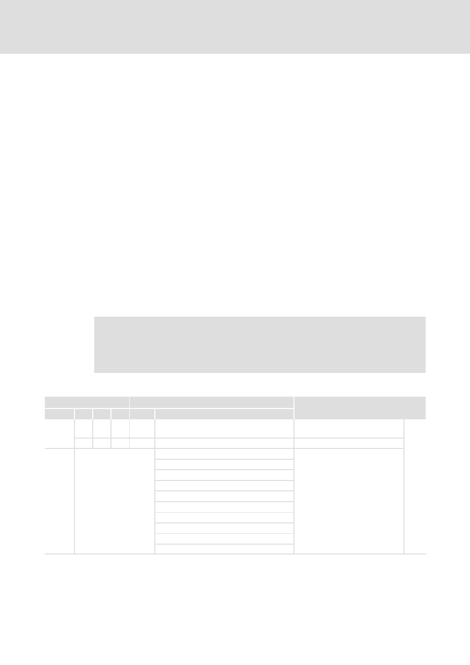
Codes for parameter setting
Code
Possible settings
Description
No.
ñò
< Byte Lenze
Selection
C0416
Level inversion for digital outputs
à outputs are LOW−active
^ 49
RW
EXT
1
0
1
255
Possible values
Add values of the inverted outputs:
e. g. DOUT1 and message bar1
negative half wave are LOW−active
à C0416 = 33.
0
No inversion
1
DOUT1
2
DOUT2
4
Reserved
8
Reserved
16
Message bar1 positive half wave
32
Message bar1 negative half wave
64
Reserved
128
Reserved