2 test commissioning with terminal control, Test commissioning with terminal control, Commissioning – Lenze 8400 BaseLine Manual User Manual
Page 90
Commissioning
Test commissioning
Test commissioning with terminal control
7
90
EDS84ABD302 EN 4.0
7.5.2
Test commissioning with terminal control
Step-by-step commissioning
1. Wiring of power terminals
Make use of the ”Electrical installation” chapter or the Mounting Instructions to wire the
power terminals according to the requirements of your device.
2. Wiring of control terminals.
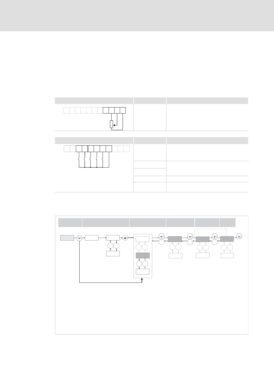
Wiring of the analog input at X4
Assignment
Terminal control
DI1
DI2
DI3
DI4
RFR
X4
24E
DO1
12I AR A1U GND
0
10V
...
1k
10k
W
...
W
A1U
Setpoint selection
10 V (=100 %):
1500 rpm (for 4-pole motor)
Wiring of the digital inputs at X4
Assignment
Terminal control
AR A1U GND
DI1
DI2
DI3
RFR
X4
DO1
12I
24E
DI4
RFR
z
Controller enable: RFR = High
z
Error reset:
High → Low (edge-controlled)
DI1
Fixed frequency 1 ... fixed frequency 3, see
below table
DI2
DI1 ... DI4: all active = High
DI3
DCB
DI4
Direction of rotation
counter-clockwise/clockwise (CCW/CW)
3. If you can be sure that the frequency inverter is in the default state (Lenze setting),
you can skip this commissioning step. If not, establish the Lenze setting of the
frequency inverter as follows:
-0-
_
`
PASS
2 sec.
0000
_ `
....
`
....
....
`
_
_
_ `
....
C002
c001
01
-1-
8888
_ `
....
84BLMEN001
z
Select menu -1- (all parameters)
z
Press ”Enter” key
z
Set C002 code
z
Press ”Enter” key
z
Set c001 subcode
z
Press ”Enter” key
z
Set value ”01”
z
Press ”Enter” key