2 terminal assignment of the power connections, Terminal assignment of the power connections, Electrical installation – Lenze 8400 BaseLine Manual User Manual
Page 67
Electrical installation
Devices in the power range from 0.37 to 3 kW (3/PE AC 400 V)
Terminal assignment of the power connections
6
67
EDS84ABD302 EN 4.0
6.4.2
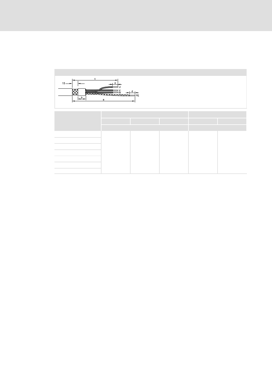
Terminal assignment of the power connections
Strip cables
X105
84BLMOTL001_a
U, V, W
PE
b
c
e
a
d
[mm]
[mm]
E84AVBxE3714
95
150
7
180
7
E84AVBxE5514
E84AVBxE7514
E84AVBxE1124
E84AVBxE1524
E84AVBxE2224
E84AVBxE3024
How to proceed:
1. Strip motor cable as specified.
2. Fold back shield of motor cable over the cable sheath. Keep unshielded cable ends as
short as possible.
3. Fix shield on the cable sheath (e.g. using a heat-shrinkable tube).
4. Fasten wire end ferrule to PE cable.
– The other cables may be wired without using wire end ferrules.
5. Connect motor cable shield to PE terminal of inverter.
– For strain relief of the cables, additional measures are required.
- p300 Mounting Instructions (12 pages)
- p300 Operating Instructions (37 pages)
- I/O system 1000 System Manual (744 pages)
- CS5800 Mounting Instructions (89 pages)
- CS5800 Operating Instructions (60 pages)
- Controller-based Automation (63 pages)
- Controller-based Automation (68 pages)
- 2121IB LECOM-Li (29 pages)
- HMI for visualisation / with control technology (96 pages)
- Controller 3200 C Operating Instructions (40 pages)
- c300 Operating Instructions (35 pages)
- EL 1800 Mounting Instructions (89 pages)
- EL 1800 Operating Instructions (57 pages)
- 3200 C (38 pages)
- 3200 C (195 pages)
- CPC 2800 Mounting Instructions (59 pages)
- CPC 2800 Operating Instructions (39 pages)
- CS 5000 DVI Mounting Instructions (86 pages)
- CS 5000 DVI Operating Instructions (53 pages)
- MP 800 DVI Mounting Instructions (88 pages)
- MP 800 Operating Instructions (43 pages)
- 8400 protec Manual (198 pages)
- 8400 motec Manual (121 pages)
- 8400 motec Mounting Instructions (164 pages)
- 9400 Manual (584 pages)
- 9400 Mounting Instructions (208 pages)
- 8400 (1494 pages)
- 8400 (304 pages)
- i700 Manual (159 pages)
- 8400 BaseLine Guide Quick Guide (10 pages)
- EZAEDE1000 (76 pages)
- EMF2180IB EthernetCAN (134 pages)
- EMF2181IB (154 pages)
- EMF2181IB (83 pages)
- EMF2177IB (28 pages)
- EMF2177IB (18 pages)
- E84AZESR RFI filter 3-29A (154 pages)
- E84AZESM Mains filter-RFI filter 42-96A (120 pages)
- ESVZAR0 RS-485 (33 pages)
- ESV SMV frequency inverter (66 pages)
- CANopen Controller-based Automation (110 pages)
- PROFIBUS Controller-based Automation (55 pages)
- EtherCAT Controller-based Automation (205 pages)
- PROFINET Controller-based Automation (44 pages)