6 relay output connection, Relay output connection, Electrical installation – Lenze 8400 BaseLine Manual User Manual
Page 80
Electrical installation
Control terminals
Relay output connection
6
80
EDS84ABD302 EN 4.0
6.5.6
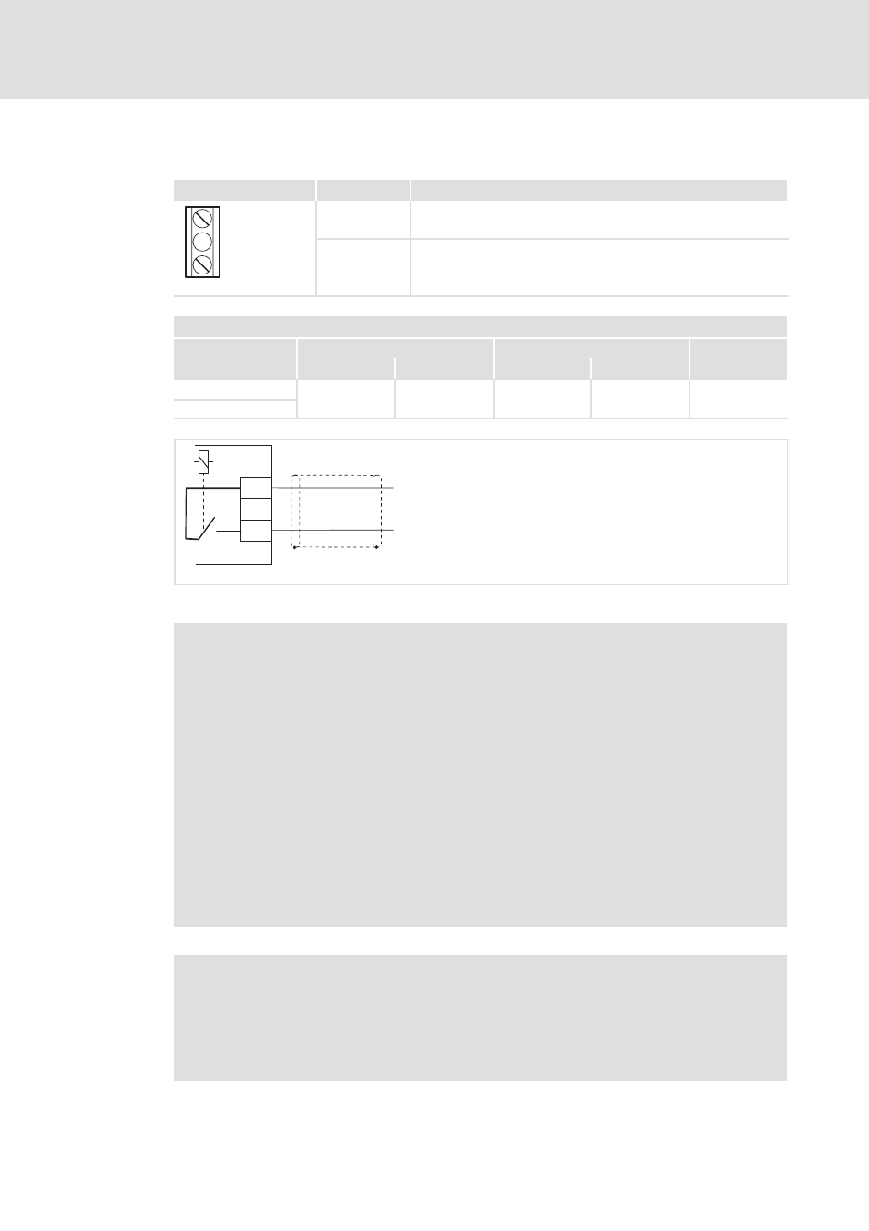
Relay output connection
Terminal X101
Labelling
Description
COM
NO
COM
Central contact of relay
NO
Relay output NO (normally open) 42
84BLGGX005
Terminal data
Max. conductor cross-section
Tightening torque
[mm
2
]
[AWG]
[Nm]
[lb-in]
flexible
0.5 ... 1.5
22 ... 16
0.5
4.5
3.5 x 0.6
with wire end ferrule
COM
X101
NO
"
"
8400GGxBLD004
Fig. 6-22
Wiring of the relay output
Note!
ƒ
Switching of control signals:
– Use shielded cables
– HF-shield termination by PE connection
– The minimum load for a correct through-connection of the relay contacts
is 10 V DC and 10 mA. Both values must be exceeded at the same time.
ƒ
Use shielded cables for switching the control signals and establish the
HF-shield termination through a PE connection.
ƒ
For the switching operation of mains potentials, shielded cables are
sufficient.
ƒ
To protect the relay contacts, use a corresponding suppressor circuit in case
of an inductive or capacitive load!
ƒ
The service life of the relay depends on the load type (ohmic, inductive, or
capacitive) and the height of capacity to be switched.
Note!
The following notes are described in detail in the Software Manual in the
section ”I/O terminals”:
ƒ
Use code C00621 to define the relay function.
ƒ
Use code C00118 to define the relay switching status.