Electrical installation – Lenze 8400 BaseLine Manual User Manual
Page 76
Electrical installation
Control terminals
Analog input
6
76
EDS84ABD302 EN 4.0
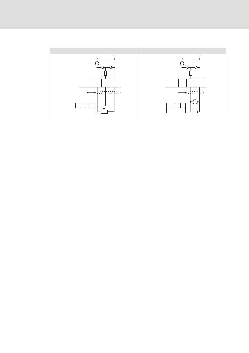
Example circuit
X4
E84AVBx...
AR A1U GND
+
10
V
-
" I/O Shields
X13
X4
-
+
E84AVBx...
AR A1U GND
+
10
V
-
" I/O Shields
X13
=
250 W
8400BLD009
8400BLD013
Fig. 6-18
Wiring examples of the analog input
Potentiometer with internal controller supply
External master current selection for a sensor signal 0 - 20 mA
X4
Terminal for the analog input and the digital inputs and output
X13
Terminal for I/O shields
GND
GND connection for analog and digital signals
See also other documents in the category Lenze Equipment:
- p300 Mounting Instructions (12 pages)
- p300 Operating Instructions (37 pages)
- I/O system 1000 System Manual (744 pages)
- CS5800 Mounting Instructions (89 pages)
- CS5800 Operating Instructions (60 pages)
- Controller-based Automation (63 pages)
- Controller-based Automation (68 pages)
- 2121IB LECOM-Li (29 pages)
- HMI for visualisation / with control technology (96 pages)
- Controller 3200 C Operating Instructions (40 pages)
- c300 Operating Instructions (35 pages)
- EL 1800 Mounting Instructions (89 pages)
- EL 1800 Operating Instructions (57 pages)
- 3200 C (38 pages)
- 3200 C (195 pages)
- CPC 2800 Mounting Instructions (59 pages)
- CPC 2800 Operating Instructions (39 pages)
- CS 5000 DVI Mounting Instructions (86 pages)
- CS 5000 DVI Operating Instructions (53 pages)
- MP 800 DVI Mounting Instructions (88 pages)
- MP 800 Operating Instructions (43 pages)
- 8400 protec Manual (198 pages)
- 8400 motec Manual (121 pages)
- 8400 motec Mounting Instructions (164 pages)
- 9400 Manual (584 pages)
- 9400 Mounting Instructions (208 pages)
- 8400 (304 pages)
- 8400 (1494 pages)
- i700 Manual (159 pages)
- 8400 BaseLine Guide Quick Guide (10 pages)
- EZAEDE1000 (76 pages)
- EMF2180IB EthernetCAN (134 pages)
- EMF2181IB (154 pages)
- EMF2181IB (83 pages)
- EMF2177IB (28 pages)
- EMF2177IB (18 pages)
- E84AZESR RFI filter 3-29A (154 pages)
- E84AZESM Mains filter-RFI filter 42-96A (120 pages)
- ESVZAR0 RS-485 (33 pages)
- ESV SMV frequency inverter (66 pages)
- CANopen Controller-based Automation (110 pages)
- PROFIBUS Controller-based Automation (55 pages)
- EtherCAT Controller-based Automation (205 pages)
- PROFINET Controller-based Automation (44 pages)