3 read_acyclic_trans, 1 structure of the response buffer, Read_acyclic_trans – EUCHNER AS-i 3.0 Command Interface User Manual
Page 21: Structure of the response buffer
AS-i 3.0 Command Interface
Commands of the Command Interface
Subject to reasonable modifications due to technical advances
Id.-No.: 102875 Issue date - 3.12.2007
EUCHNER GmbH + Co. KG
Kohlhammerstraße 16, D-70771 Leinfelden-Echterdingen
Tel. +49/711/7597-0, Fax +49/711/753316
21
4.3.3
READ_ACYCLIC_TRANS
With this call the response of the transfer command (started with
WRITE_ACYCLIC_TRANS) is read.
The response data have the same format, as by commands RD_74_75_PARAM,
RD_74_75_ID and „safety at work“-monitor diagnostics
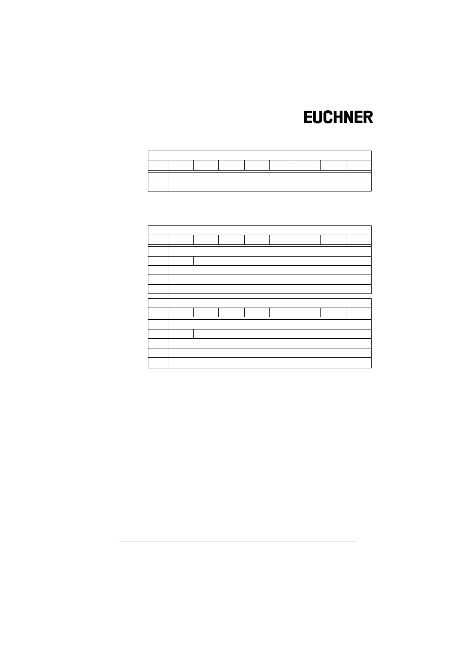
4.3.3.1
Structure of the response buffer
As the string to be transferred can be longer than the command interface, the
string is first saved in a buffer that can be read in sections using the buffer index (i).
The first byte in the response buffer defines the current command. FF
16
signifies
transfer still active, FE
16
signifies transfer interrupted with errors. In the correct
case, the command from WRITE_ACYC_TRANS is given here.
The first sub-section of the string is read using i
≡ 0, the second with i = n-2, etc.
The two following bytes (high, low) define the length of the response buffer.
Response
Byte
2
7
2
6
2
5
2
4
2
3
2
2
2
1
2
0
1
4E
16
2
return
Request
Byte
2
7
2
6
2
5
2
4
2
3
2
2
2
1
2
0
1
4F
16
2
T
circuit
3
slave address
4
buffer index (i) high
5
buffer index (i) low
Response
Byte
2
7
2
6
2
5
2
4
2
3
2
2
2
1
2
0
1
4F
16
2
T
response
3
data i
...
...
m
1
1. command interface response length m
data i+(m-2)