Despatch P1400+ Temperature Controller User Manual
Page 94
88
Self-Tune
Type: Controller Tuning Definition
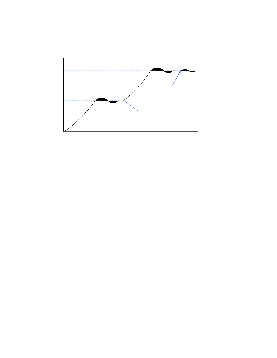
Self-Tune continuously optimises tuning while a controller is operating. It uses a pattern recognition
algorithm, which monitors the process error (deviation). The diagram shows a typical application
involving a process start up, setpoint change and load disturbance.
Figure 39. Self-Tune Operation
The deviation signal is shown shaded and overshoots have been exaggerated for clarity. The Self-
Tune algorithm observes one complete deviation oscillation before calculating a set of PID values.
Successive deviation oscillation causes values to be recalculated so that the controller rapidly
converges on optimal control. When the controller is switched off, the final PID terms remain stored
in the controller's non-volatile memory, and are used as starting values at the next switch on. The
stored values may not always be valid, if for instance the controller is brand new or the application
has been changed. In these cases the user can utilise Pre-Tune to establish new initial values.
Use of continuous self-tuning is not always appropriate for applications which are frequently
subjected to artificial load disturbances, for example where an oven door is likely to be frequently left
open for extended periods of time.
The Self-Tune feature on Valve Motor Drive controllers always sets the Rate parameter to zero
(OFF) because derivative action is not usually desirable in these applications.
Self-Tune cannot be engaged if a controller is set for On-Off Control.
Also refer to
Minimum Motor On Time
,
On-Off Control
,
Pre-Tune
,
PID
, and
Tuning
.
Serial Communications Option
Type: General Definition
An feature that allows other devices such as PC’s, PLC’s or a master controller to read or change an
instruments parameters via an RS485 Serial link. Full details can be found in the Serial
Communications sections of this manual.
Also refer to
Controller
,
Indicator
,
Master & Slave
,
Limit Controller
and
PLC
Set Valve Closed Position
Type: VMD Controller Parameter
When Valve Position Indication is to be used on Valve Motor Controllers, this parameter defines the
input value that will be measured by the Auxiliary Input, when the valve is fully closed. The valve
must driven to its “Closed” end stop before setting this parameter.
It must not be used to limit valve movement, separate Valve Close and Open Limit parameters are
available for this purpose.
Display code =
PcUL
, default setting = Auxiliary Input Range Minimum.
Also refer to
Auxiliary Input
,
Set Valve Opened Position
,
Valve Close Limit
,
Valve Open Limit
,
Valve Motor Control
and
Valve Position Indication
.
T
e
m
p
e
ra
tu
re
Setpoint 1
Setpoint Change
Load Disturbance
Time
Setpoint 2