Despatch P1400+ Temperature Controller User Manual
Page 32
26
SECTION 6: MESSAGES AND ERROR INDICATIONS
The following displays are shown when an error occurs or a hardware change is detected.
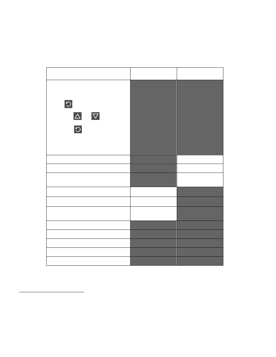
Table 4.
Error/Faults conditions
Error/Faults Conditions
Upper display
Lower Display
(where fitted)
Configuration & Setup is required.
Seen at first turn on or if hardware
configuration changed.
Press to enter Configuration
Mode,
next press or to enter the
unlock code number,
then press to proceed.
Configuration must be completed
before return to operator mode is
allowed
1
Goto
ConF
Input more than 5% over-range
2
[
HH
]
*
Normal Display
Input more than 5% under-range
3
[
LL
]
*
Normal Display
Sensor Break. Break detected in
the input sensor or wiring
OPEN
*
Normal Display
Auxiliary input over-range
Normal Display
[
HH
]
*
Auxiliary input under-range
Normal Display
[
LL
]
*
Auxiliary Break. Break detected in
the auxiliary input
Normal Display
OPEN
*
Option 1 module fault.
Err
Opn1
Option 2 module fault.
Err
Opn2
Option 3 module fault.
Err
Opn3
Option A module fault.
Err
OpnA
Option B module fault.
Err
Opnb
* Note
Input sensor and Auxiliary over/under-range or break indications will be seen wherever these
values would normally be displayed.
1
This feature does not guarantee correct configuration. It only helps to ensure that the unit will be configured
before use. Use of set-up mode is not enforced but may be essential for the users application.
2
If the PV display exceeds
9999
before 5% over-range is reached, an over-range indication is given.
3
Indicators will allow up to 10% under-range on non-zero based Linear ranges. If the PV display is less than
−1999
before the % under-range is reached, an under-range indication is given.