Despatch P1400+ Temperature Controller User Manual
Page 54
48
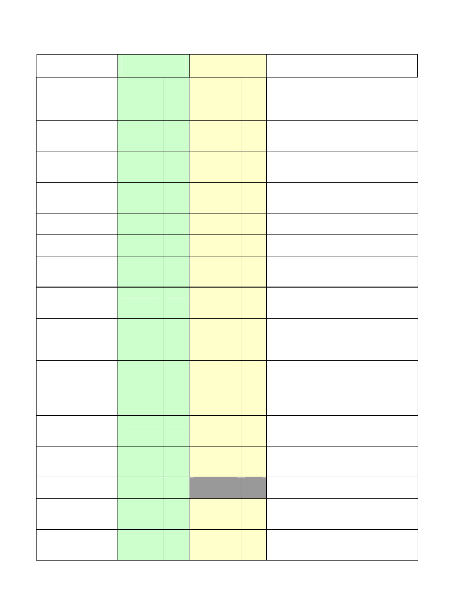
Parameter
Modbus
Parameter No.
ASCII Ident &
Message Types
Notes
Rate
9
R/W
D
Type 2, 3/4
R/W
Derivative Time Constant value.
Read only if Self-Tuning.
ASCII range: 0 to 99m 59secs. (99.59)
Modbus range: 0 to 5999
Output 1
Cycle time
10
R/W
N
Type 2
Type 3/4
RO
R/W
0.5, 1, 2, 4, 8, 16, 32, 64,128, 256 or
512 seconds.
Scale Range
Lower Limit
11
R/W
H
Type 2
Type 3/4
RO
R/W
Lower limit of scaled input range
Scale Range
Upper Limit
12
R/W
G
Type 2
Type 3/4
RO
R/W
Upper limit of scaled input range
Alarm 1 Value
13
R/W
C
Type 2, 3/4
R/W
Alarm 1 active at this level
Alarm 2 Value
14
R/W
E
Type 2, 3/4
R/W
Alarm 2 active at this level
Manual Reset
15
R/W
J
Type 2, 3/4
R/W
Bias value. 0% to 100% for single
control output or
-100% to +100% for dual outputs
Overlap /
Deadband
16
R/W
K
Type 2, 3/4
R/W
20% to +20% of
PB_P
+
PB_S
;
Negative value = Deadband
Positive value = Overlap
On / Off Differential
17
R/W
F
Type 2, 3/4
R/W
0.1% to 10.0% of input span
Used for Primary output on/off
differential and for combined Primary
and Secondary on/off differential.
Decimal Point
Position
18
R/W
Q
Type 2
Type 3/4
RO
R/W
0 = xxxx
1 = xxx.x
2 = xx.xx
3 = x.xxx
Read only if not Linear Input.
Output 2
Cycle Time.
19
R/W
O
Type 2
Type 3/4
RO
R/W
0.5, 1, 2, 4, 8, 16, 32, 64,128, 256 or
512 seconds.
Primary Output
Power Limit
20
R/W
B
Type 2
Type 3/4
RO
R/W
Safety power limit; 0 to 100 %.
Actual Setpoint
21
RO
Current (ramping) value of selected
setpoint.
Setpoint Upper
Limit
22
R/W
A
Type 2
Type 3/4
RO
R/W
Maximum setpoint value. Current SP
to Input Range Maximum
Setpoint Lower
Limit
23
R/W
T
Type 2
Type 3/4
RO
R/W
Minimum setpoint value. Current SP
to Input Range Minimum