Despatch P1400+ Temperature Controller User Manual
Page 42
36
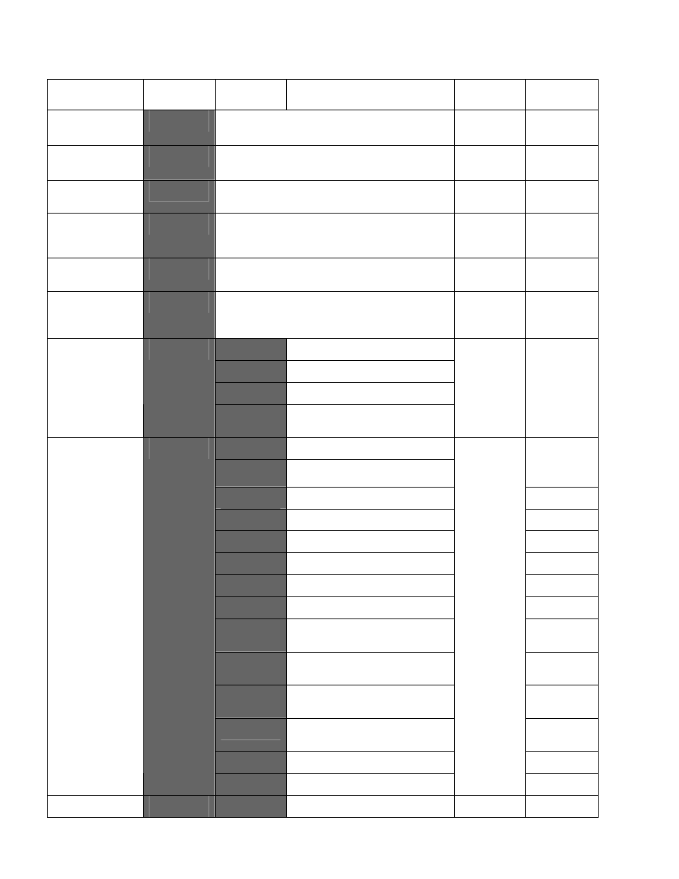
Parameter
Lower
Display
Upper
Display
Description
Default
Value
When
Visible
Process Low
Alarm 2 value*
PLA2
Range Min. to Range Max.
Parameter repeated in Setup Mode
Range
Min.
ALA2 =
P_Lo
Deviation
Alarm 2 Value*
dAL2
±
span from setpoint.
Parameter repeated in Setup Mode
5
ALA2 =
dE
Band Alarm 2
value*
bAL2
1 LSD to full span from setpoint.
Parameter repeated in Setup Mode
5
ALA2 = b
And
Alarm 2
Hysteresis*
AHY2
1 LSD to 100% of span (in display units)
on “safe” side of alarm point.
Parameter repeated in Setup Mode
1
Always
Loop Alarm
Enable
LAEn
disA
(disabled) or
EnAb
(enabled)
disA
Always
Loop Alarm
Time*
LATi
1 sec to 99 mins. 59secs
Only applies if primary proportional
band = 0
99
.
59
LAEn =
EnAb
none
No alarms Inhibited
ALA1
Alarm 1 inhibited
ALA2
Alarm 2 inhibited
Alarm Inhibit
Inhi
both
Alarm 1 and alarm 2
inhibited
none
Always
Pri
Primary Power
Sec
Secondary Power
Opn1
is not
none
Al_d
Alarm 1, Direct Acting
Not linear
A1_r
Alarm 1, Reverse Acting
Not linear
A2_d
Alarm 2, Direct Acting
Not linear
A2_r
Alarm 2, Reverse Acting
Not linear
LP_d
Loop Alarm, Direct Acting
Not linear
LP_r
Loop Alarm, Reverse Acting
Not linear
Or_d
Logical Alarm 1 OR Alarm 2
Direct Acting
Not linear
Or_r
Logical Alarm 1 OR Alarm 2
Reverse Acting
Not linear
Ar_d
Logical Alarm 1 AND Alarm
2, Direct Acting
Not linear
Ar_r
Logical Alarm 1 AND Alarm
2, Reverse Acting
Not linear
retS
Retransmit SP Output
Linear only
Output 1
Usage
USE1
retP
Retransmit PV Output
Pri
Linear only
Linear Output
tYP1
0_5
0 to 5 V DC output 1
0_10
Opn1 =