Despatch P1400+ Temperature Controller User Manual
Page 53
47
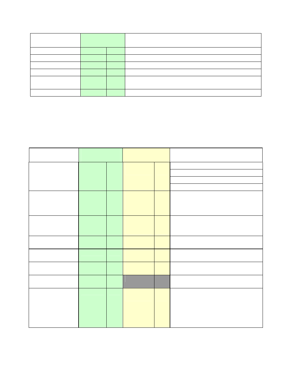
Parameter
Modbus
Parameter No.
Notes
Alarm 1 Status
5
RO
1 = Active, 0 = Inactive
Alarm 2 Status
6
RO
1 = Active, 0 = Inactive
Setpoint Ramping
7
R/W
1 = Enable(d), 0 = Disable(d)
Loop Alarm Status
10
R/W
1 = Active/Enable, 0 = Inactive/Disable
Loop Alarm
12
R/W
Read to get loop alarm status. Write 0/1 to
disable/enable.
Digital Input 2
13
RO
State of Option B digital input.
To set the bit value to 1 write FF, to set the bit value to 0 write 00. Refer to Function Code 05 in the
Modbus Communications section.
Word Parameters
Table 14.
1400+ Communications - Word Parameters
Parameter
Modbus
Parameter No.
ASCII Ident &
Message Types
Notes
Current value of PV.
If under-range = 62976 (5 ASCII)
If over-range = 63232 (0 ASCII)
Process Variable
1
RO
M
Type 2
RO
If Sensor break = 63488 (ASCII = n/a)
Setpoint
2
R/W
S
Type 2
Type 3/4
RO
R/W
Value of currently selected setpoint.
(Target setpoint if ramping).
Parameter is read only if the current
setpoint is RSP.
Output Power
3
R/W
W
Type 2
Type 3/4
RO
R/W
0% to 100% for single output;
−
100%
to +100% for dual output control.
Read Only if not in manual control.
Deviation
4
RO
V
Type 2
RO
Difference between Process Variable
and Setpoint (value = PV-SP)
Secondary
Proportional Band
5
R/W
U
Type 2, 3/4
R/W
Adjustable 0.0% to 999.9% of input
span. Read only when Self-Tuning.
Primary
Proportional Band
6
R/W
P
Type 2, 3/4
R/W
Adjustable 0.0% to 999.9% of input
span. Read only when Self-Tuning.
Direct / Reverse
Acting
7
R/W
1 = Direct Acting, 0 = Reverse
Automatic Reset
Time
(or Loop Alarm
Time)
8
R/W
I
Type 2, 3/4
R/W
Integral Time Constant value.
(or Loop Alarm Time value in ON/OFF
control mode if Loop Alarm Enabled)
Read only if Self-Tuning.
ASCII range: 0 to 99m 59sec (99.59)
Modbus range: 0 to 5999