Despatch P1400+ Temperature Controller User Manual
Page 14
8
CAUTION:
Take care not to put undue stress on the ribbon cable attaching the display and CPU
boards.
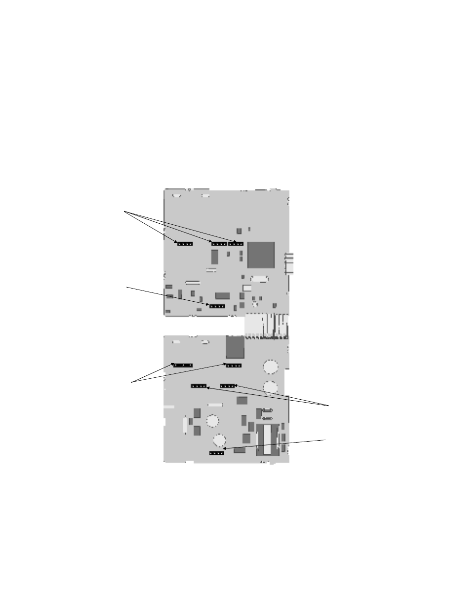
2. Remove or fit the modules into the Option slots as required. The location of the connectors is
shown below. Tongues on each option module locate into a slots cut into the main boards,
opposite each of the connectors.
Figure 6. Option Module Connectors -
1
/
4
DIN Instruments
CAUTION:
Check for correct orientation of the modules and that all pins locate correctly into the
socket
Option Slot 2
Connector PL4A
Option Slot A
Connectors PL5 & PL6
Option Slot B
Connectors PL2A,
PL2B & PL2C
Option Slot 3
Connectors PL4B
Option Slot 1
Connectors PL7 & PL8