Despatch P1400+ Temperature Controller User Manual
Page 55
49
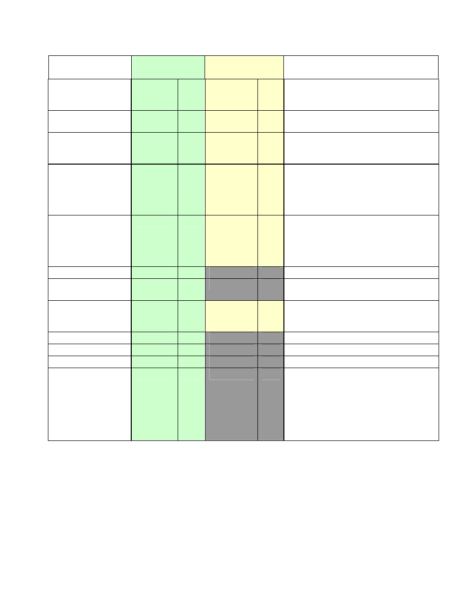
Parameter
Modbus
Parameter No.
ASCII Ident &
Message Types
Notes
Setpoint Ramp
Rate
24
R/W
^
Type 2
Type 3/4
RO
R/W
0 = 0ff, 1 to 9999 increments / hour.
Dec Point position as for input range.
Input Filter Time
Constant
25
R/W
m
Type 2, 3/4
R/W
0 to 100 seconds
Process Value
Offset
26
R/W
v
Type 2
Type 3/4
RO
R/W
Modified PV = Actual PV + PV Offset.
Limited by Scale Range Maximum
and Scale Range Minimum.
Re-transmit Output
Maximum
27
R/W
[
Type 2, 3/4
R/W
Maximum scale value for retransmit
output, 1999 to 9999. This parameter
applies to the first re-transmit output
fitted (see also Modbus parameters
2214, 2224 & 2234).
Re-transmit Output
Minimum
28
R/W
\
Type 2, 3/4
R/W
Minimum scale value for retransmit
output, 1999 to 9999. This parameter
applies to the first re-transmit output
fitted (see also Modbus parameters
2215, 2225 & 2235).
Setpoint 2
29
R/W
Value of Setpoint 2
Remote Setpoint
30
RO
Value of Remote Setpoint. Returns
0FFFFhex if RSP not fitted.
Remote Setpoint
Offset
31
R/W
~
Type 2, 3/4
R/W
Modified RSP = Actual RSP + RSP
Offset. Limited by Scale Range
Maximum and Scale Range Minimum.
Alarm 1 Hysteresis
32
R/W
0 to 100% of span
Alarm 2 Hysteresis
33
R/W
0 to 100% of span
Setpoint 1
34
R/W
Value of Setpoint 1
Setpoint Select
35
R/W
Shows which is the currently selected
active setpoint. If a digital input has
been configured for Setpoint Select, it
will take priority over this parameter
1 = SP1 or LSP
2 = SP2
100hex = RSP