Despatch P1400+ Temperature Controller User Manual
Page 47
41
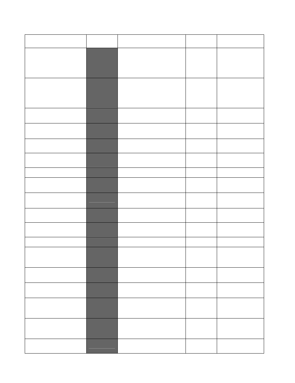
Parameter
Lower
Display
Upper Display
Adjustment Range
Default
Value
When
Visible
Output 2
Cycle Time
CT2
0.5, 1, 2, 4, 8, 16, 32, 64,
128, 256 or 512 secs.
Not applicable to linear
outputs
32
32
32
32
USE2
= Pri
or
Sec
or
bus
Output 3
Cycle Time
CT3
0.5, 1, 2, 4, 8, 16, 32, 64,
128, 256 or 512 secs.
Not applicable to linear
outputs
32
32
32
32
USE3
= Pri
or
Sec
or
bus
Process High Alarm 1
value*
PhA1
Range Min. to Range
Max.
Range
Max.
ALA1
= P_Hi
Process Low Alarm 1
value*
PLA1
Range Min. to Range
Max.
Range
Min.
ALA1
=
P_Lo
Deviation Alarm 1
Value*
dAL1
±
span from setpoint
5555
ALA1
=
dE
Band Alarm 1 value*
bAL1
1 LSD to full span from
setpoint.
5555
ALA1
=
bAnd
Alarm 1 Hysteresis*
AHY1
Up to 100% of span
1111
Always
Process High Alarm 2
value*
PhA2
Range Min. to Range
Max.
Range
Max.
ALA2
=
P_Hi
Process Low Alarm 2
value*
PLA2
Range Min. to Range
Max.
Range
Min.
ALA2
=
P_Lo
Deviation Alarm 2
Value
dAL2
±
span from setpoint
5555
ALA2
=
dE
Band Alarm 2 value*
bAL2
1 LSD to full span from
setpoint.
5555
ALA2
=
bAnd
Alarm 2 Hysteresis*
AHY2
Up to 100% of span
1111
Always
Loop Alarm Time*
LATi
1 sec to 99 mins. 59secs.
Only applies if primary
proportional band = 0
99.59
99.59
99.59
99.59
LAEn
=
EnAb
Auto Pre-tune enable /
disable
APT
diSA
disabled or
EnAb
enabled
diSA
Always
Manual Control select
enable / disable
PoEn
diSA
disabled or
EnAb
enabled
diSA
Always
Setpoint Select shown
in Operator Mode,
enable / disable
SSEn
diSA
disabled or
EnAb
enabled
diSA
Slot A or B fitted
with RSP module
Setpoint ramp shown in
operator mode, enable /
disable
Spr
diSA
disabled or
EnAb
enabled
diSA
Always
SP Ramp Rate Value
rP
1 to 9999 units/hour or Off
(blank)
Blank
Always