1 counter offsets, 1 horizontal and vertical offset example, An269 – Cirrus Logic AN269 User Manual
Page 5
AN269
AN269REV1
5
When the output of the horizontal down counter rolls over, it will decrement the vertical down counter at one count
per horizontal line. When the count reaches 0, the vertical down counter loads the value contained in the VLinesTo-
tal register, and continues counting down. The VCSYNC output is generated by comparing the value of the vertical
down counter with the VSyncStrtStop register. If the value of the counter is in the active range (VSyncStrtStop.Start
> Vertical Counter > VSyncStrtStop.Stop), the VCSYNC output becomes active. Similarly the VBlankStrtStop, VAc-
tiveStrtStop, and VClkStrtStop values are compared with the vertical down counter, and then control the BLANK
Output, Pixel Output Enable, and Pixel Clock Output Enable (once combined with the appropriate signals from the
horizontal timing block).
4.1
Counter Offsets
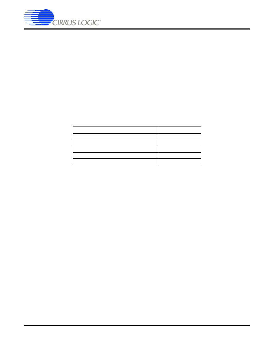
Due to internal delays inside the raster timing block, various register settings must be offset to align data,
sync, and clock outputs properly at the output of the ep93xx. In the following sections, these delays are add-
ed at the last stage of computing the timings (when setting the actual register values).
These delays are listed in
4.1.1
Horizontal and Vertical Offset Example
Given the following:
Screen Width = 16 Pixels
Screen Height = 1 Line
Screen Resolution = 16 bpp, 565.
Total Number of Horizontal Clocks = 20
Two Lines in the vertical direction
The Start of HSync signal,Blank and Vsync signal and start of data coming out must line up.
Registers
Offset in SPClocks
HSYNCSTARTSTOP
0
HACTIVESTRTSTOP
-1
HACTIVESTRTSTOP (2 2/3 pixel mode)
0
HBLANKSTRTSTOP
-1
HCLKSTRTSTOP
-6
Table 2. Offsets for Horizontal and Vertical Counters