An269 – Cirrus Logic AN269 User Manual
Page 37
AN269
AN269REV1
37
Now, the number of VIDCLK periods required for the active region (i.e., region with valid pixel data) can
be determined. In the following equation, ActiveVidClks represents the total number of VIDCLKs that will
occur while outputting pixel data (there is usually 1 VIDCLK per pixel):
ActiveVidClks = (VIDCLKs/Pixel) * (horizontal resolution)
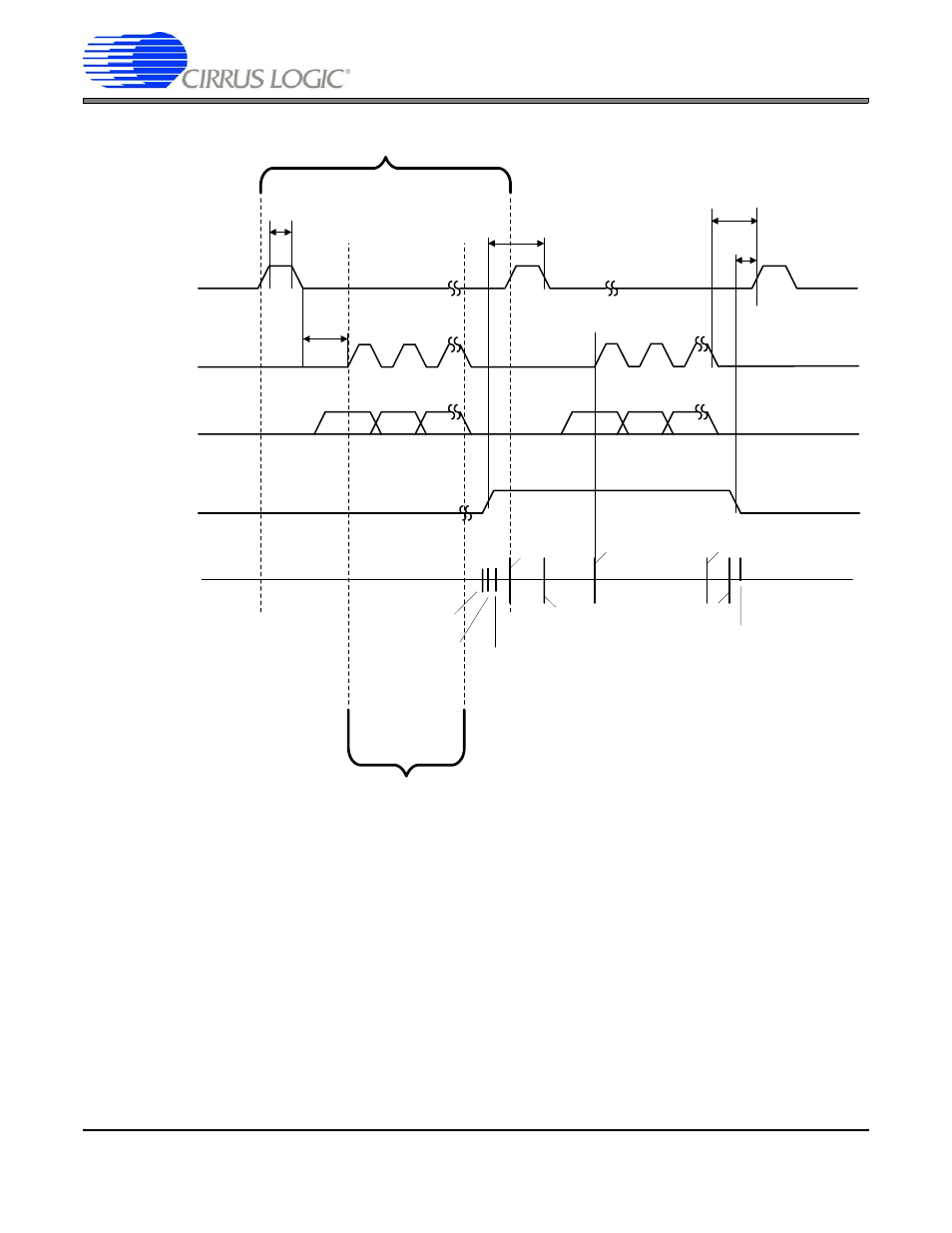
We will now discuss each of the regions in more detail. Each region is labeled by the appropriate length
of time, in VIDCLKs. A diagram of this is shown in
. The time from VCSYNC signal becoming
active until the HSYNC signal becomes active (on the second line) is noted as the FrameHoldVidClks.
The time from the HSYNC signal becoming active to the time it becomes inactive is LoadHighVidClks.
The time from HSYNC becoming inactive until the first valid SPCLK is LoadCPVidClks. This will guarantee
HSYNC
SPCLK
t
HSYNCH
Single Horizontal Line
DATA
One SPCLK per Horizontal Pixel
VCSYNC
(Horizontal
Line 1 ONLY)
t
HSYNCSPCLK
t
SPCLKHSYNC
t
HVCSYNC
t
VCHHSYNC
t
VCLHSYNC
Count = HClkTotal
Count = 0
Horizontal Line
Counter Value
HSyncStart
HSyncStop
HSyncStop
HActiveStart
HActiveStop
Count = HClkTotal - 1
Count = HClkTotal
Count = 0
Figure 19. Horizontal Line for Frame Type 2 Displays