Cirrus Logic AN269 User Manual
Page 4
4
AN269REV1
AN269
4. USING THE HORIZONTAL AND VERTICAL COUNTER FOR TIMING-
SIGNAL GENERATION
Conceptually, all timing synchronization outputs from the EP93xx are driven from a series of down counters followed
by combinational logic. The input clock to these counters is the video clock signal, VIDCLK (see
Video Clock, VIDCLK” on page 2
). There are two banks of down counter/comparators - one for horizontal and one
for vertical timing generation. A block diagram of the horizontal and vertical timing generation is shown in
,
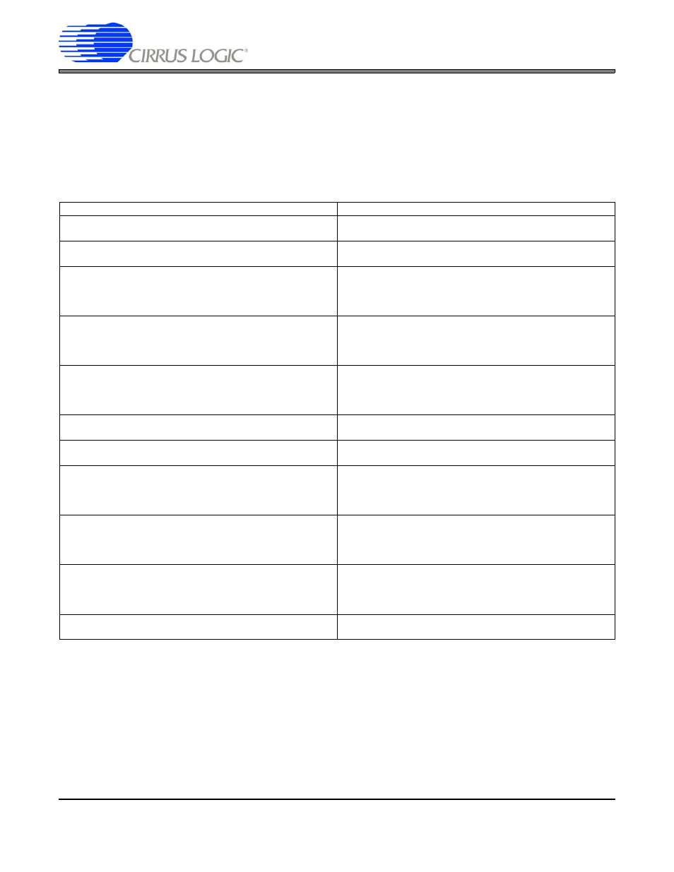
and brief descriptions of each of the corresponding timing registers are found in
The video clock (VIDCLK) decrements the horizontal down counter at one count per video clock period. When the
count reaches 0, the counter loads the value contained in the HClkTotal register, and continues counting down. The
HSYNC output is generated by comparing the value of the horizontal down counter with the HSyncStrtStop register.
If the value of the counter is in the active range (HSyncStrtStop.Start > Horizontal Counter > HSyncStrtStop.Stop),
the HSYNC output becomes active. Similarly, the HBlankStrtStop, HActiveStrtStop, and HClkStrtStop values are
compared with the horizontal down counter, and then control the BLANK Output, Pixel Output Enable, and Pixel
Clock Output Enable (once combined with the appropriate signals from the vertical timing block).
REGISTER
DESCRIPTION
VLINESTOTAL
Vertical Lines Total
Total number of horizontal lines in a single video frame (Includ-
ing SYNC, BLANK & ACTIVE regions).
VSYNCSTRTSTOP
Vertical Sync Pulse Start/Stop
Vertical counter: Defines when the VCSYNC pulse becomes
active (Start) and goes inactive (Stop)
VACTIVESTRTSTOP
Vertical Active Start/Stop
Vertical counter: Defines when the VACTIVE signal becomes
active (Start) and goes inactive (Stop). This internal signal is
OR’d with HACTIVE to define the active portion of the video
frame (when active pixel data is clocked out).
VBLANKSTRTSTOP
Vertical Blank Start/Stop
Vertical counter: Defines when the VBLANK signal becomes
active (Start) and becomes inactive (Stop) before and after the
active video portion of the video frame. BLANK is the AND of
HBLANK and VBLANK.
VCLKSTRTSTOP
Vertical Clock Start/Stop
Vertical counter: Defines when the VCLKEN Signal goes active
(Start) and becomes inactive (Stop) at the beginning or end of
the video frame. SPCLK is only generated when the VCLKEN
and HCLKEN signals are BOTH active.
HLINESTOTAL
Horizontal Lines Total
Total Number of VIDCLKs in a single horizontal line of video,
including both active and inactive regions.
HSYNCSTRTSTOP
Horizontal Sync Pulse Start/Stop
Horizontal counter: Defines when the HSYNC pulse becomes
active (Start) and goes inactive (Stop).
HACTIVESTRTSTOP
Horizontal Active Start/Stop
Horizontal counter: Defines when the HACTIVE signal
becomes active (Start) and goes inactive (Stop). This signal is
OR’d with VACTIVE to define the active portion of the video
frame (when active pixel data is clocked out).
HBLANKSTRTSTOP
Horizontal Blank Start/Stop
Horizontal counter: Defines when the HBLANK signal
becomes active (Start) and becomes inactive (Stop) before
and after the active video portion of the video frame. BLANK is
the AND of HBLANK and VBLANK.
HCLKSTRTSTOP
Horizontal Clock Start/Stop
Horizontal counter: Defines when the HCLKEN Signal goes
active (Start) and becomes inactive (Stop) at the beginning or
end of the video frame. SPCLK is only generated when the
VCLKEN and HCLKEN signals are BOTH active.
VIDEOATTRIBS
Video Signal Attributes
Synchronization Control, Polarity Selection, Output Enables,
etc.
Table 1. Summary of Synchronization Registers