Own in, Figure 13, An269 – Cirrus Logic AN269 User Manual
Page 23
AN269
AN269REV1
23
then counts down by 1 for each HSYNC time period, regardless of whether SPCLK/DATA is present or
not. When the counter reaches 0, it is reset to VLinesTotal.
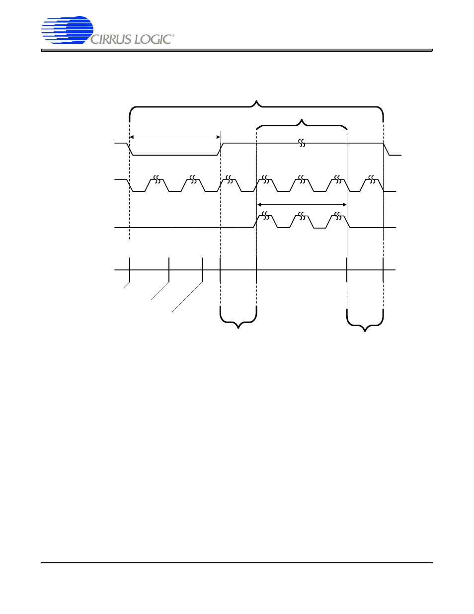
Next we will determine the appropriate time for the VCSYNC signal to become active. As can be seen
from the diagram, VCSYNC becomes active when the line counter is reset to VLinesTotal (the beginning
of the frame). VCSYNC becomes inactive after the period of tVSYNC has elapsed. Therefore, the VSYNC
signal should become inactive when the line counter is VLinesTotal-tVSYNC. This is shown using the
equations below, where VSyncStart is the point at which VCSYNC becomes active and VSyncStop is the
point at which VCSYNC becomes inactive (again, all time is measured in horizontal line periods):
VSyncStart = VLinesTotal
VSyncStop = VLinesTotal – tVSYNC
The active data/blank signal becomes active when valid data starts, and inactive once the valid data
stops. Therefore, when the vertical line counter reaches the end of the back porch interval, it should be-
come active. At the beginning of the front porch interval, it should become inactive. The following equa-
tions show this, using VBlankStart as the position at which this signal becomes active, and VBlankStop
as the position at which this signal becomes inactive (VBlankStop is 1 less than tVFRONTPORCH due to
0-based counter implementation):
VBlankStart = VLinesTotal - tVSYNC - tVBACKPORCH
VBlankStop = tVFRONTPORCH - 1
t
VSYNC
VCSYNC
HSYNC
Single Video Frame
t
VACTIVE
BLANK
Back Porch Interval t
VBACKPORCH
Front Porch Interval t
VFRONTPORCH
Vertical Line
Counter Value
Count = VLinesTotal
Count = VLinesTotal - 1
Count = VLinesTotal - 2
Count =0
Active Video
Figure 13. HSYNC/VSYNC Video Frame with Register Timing