Generation of the video clock, vidclk, An269 3. generation of the video clock, vidclk – Cirrus Logic AN269 User Manual
Page 2
2
AN269REV1
AN269
3. GENERATION OF THE VIDEO CLOCK, VIDCLK
The internal video clock (VIDCLK), which drives the raster engine and the external pixel clock (SPCLK), is derived
from PLL1, PLL2, or the external clock input. The SPCLK signal clocks data from the EP93xx into the external LCD
or display. The number of pixels per SPCLK may be 1, 2, 4, 8, or 2-2/3.
Conceptually, the external clock (SPCLK) is generated by dividing the VIDCLK by the appropriate clock divider. The
necessary divider depends on the output mode. For 1 pixel-per-SPCLK, there will be 1 VIDCLK-per-SPCLK. For 2
pixels-per-SPCLK, there will be 2 VIDCLKs-per-SPCLK (SPCLK runs at VIDCLK/2). For the case of 4 pixels-per-
SPCLK, there are 4 VIDCLKs-per-SPCLK. Note that 2-2/3 mode is a special case in which there are 3 VIDCLKs for
the first SPCLK, 2 for the second SPCLK, and 3 for the third SPCLK. This pattern then repeats every 8 pixels (and
therefore 8 VIDCLKs).
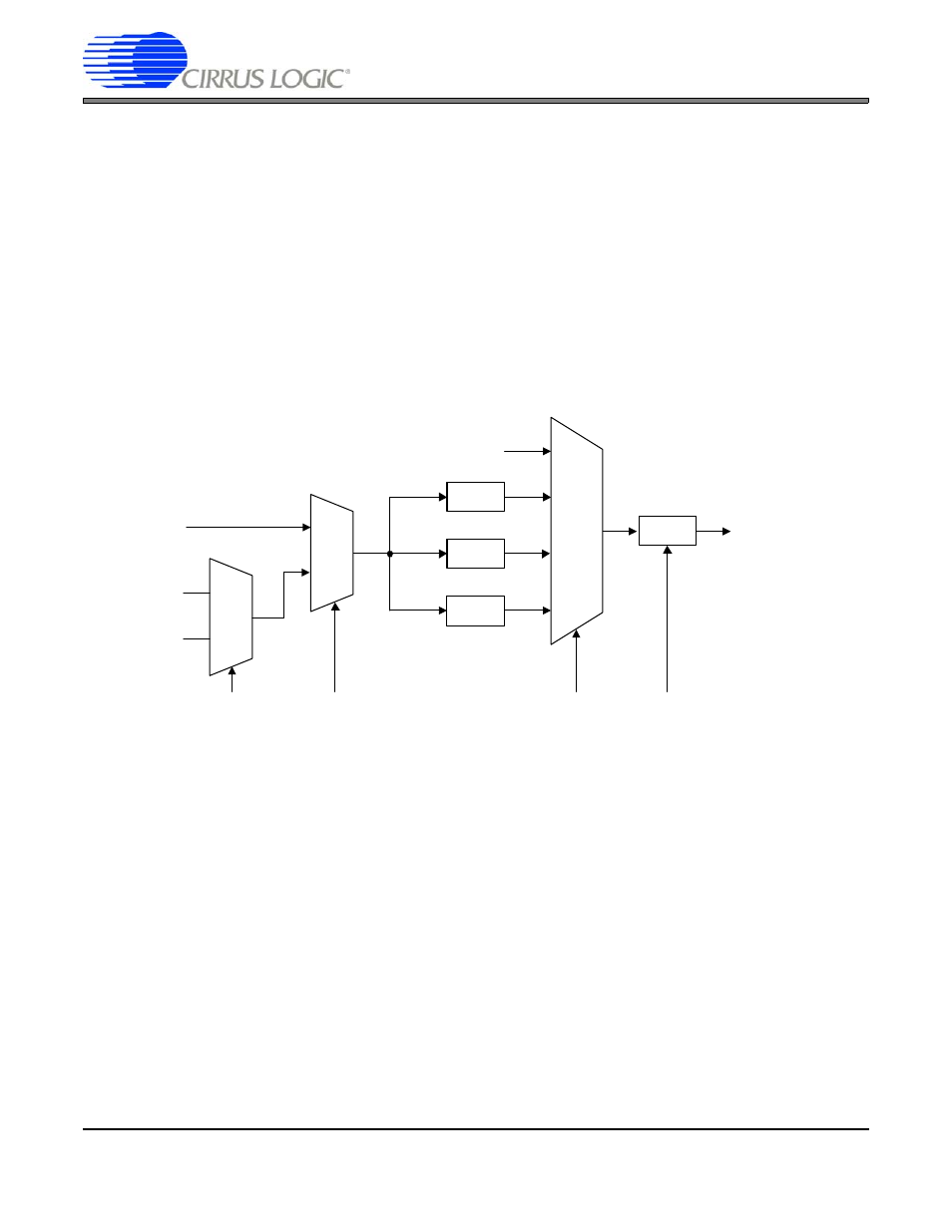
To derive VIDCLK, the clock source (PLL1, PLL2, or External Clock) is divided by a prescaler and then by a divide-
by-N block, where N
≥
2. This is shown in the block diagram in
. The values of PSEL, ESEL, PDIV, and
VDIV are all bit fields of the VidClkDiv register, contained in the system controller. Please refer to the EP93xx User’s
Guide (“System Controller” section) for more information on the VidClkDiv register.
Below is one algorithm for integer math operations (similar to the Linux 2.6 video display driver) for determining the
proper VidClkDiv settings for a desired VIDCLK rate. Essentially, the algorithm examines the frequency of the ex-
ternal clock source, PLL1, and PLL2, and then attempts different combinations of the divider settings to find a setting
that generates the smallest error. The divider settings are a combination of PDIV (pre-divider) and VDIV (divide-by-
N). Since PDIV can be set to 2, 2.5, or 3, the algorithm uses twice that value (and therefore twice the value of the
PLL1, PLL2, etc.). Note that the accuracy of this algorithm may be improved through the use of floating-point math.
ч 2.5
ч 2
ч 3
00
01
10
0
1
PLL1
PSEL
External
Clock
0
1
ESEL
PLL2
Disable
11
PDIV
÷ N
Video Clock
Output
(To Raster
Block)
VDIV
(
≥ 2)
Figure 1. Video Clock Generation