Setting up display timing, 1 hsync/vsync-style displays, Section 6 – Cirrus Logic AN269 User Manual
Page 16: An269 6. setting up display timing
16
AN269REV1
AN269
6. SETTING UP DISPLAY TIMING
6.1
HSYNC/VSYNC-Style Displays
In displays using a HSYNC/VSYNC-style timing interface, the following control signals are commonly used
for data synchronization:
–
DCLK - Data Input Clock. Usually one rising/falling edge occurs per pixel or set of pixel data. This is
the highest frequency interface signal, and transitions occur many times during each horizontal line.
–
DE - Data Enable or Valid. Used to indicate valid data is currently being clocked into the display.
This may be referred to as a blanking signal, and will become active one time per valid line.
–
VSYNC - Vertical Synchronization Signal. Indicates the beginning of a full frame of data. This signal
becomes active one time during one frame if in progressive mode, or two times per frame in
interlaced mode.
–
HSYNC - Horizontal Synchronization Signal. Indicates the beginning of the next horizontal line. This
signal becomes active one time during the line, and many times per frame.
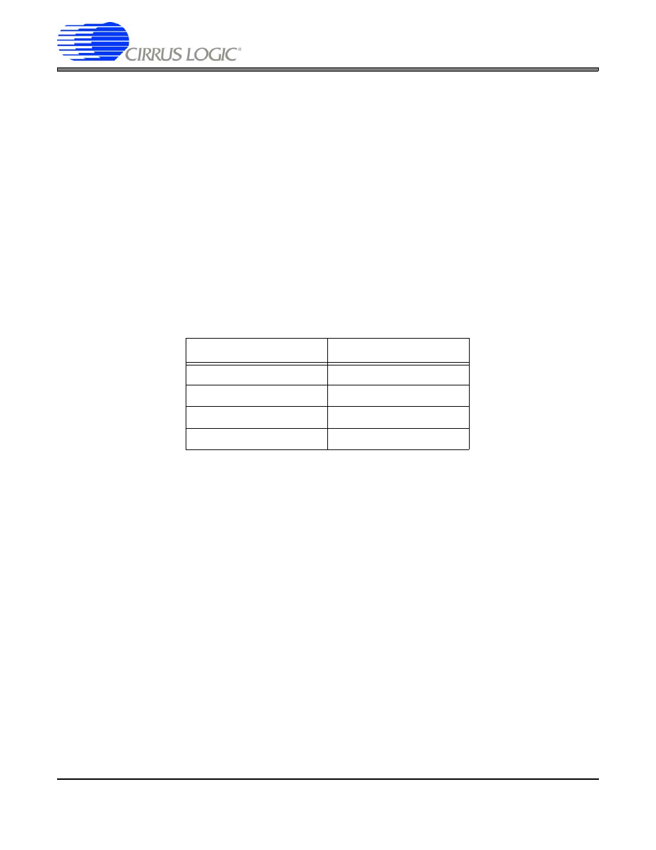
These signals should be connected to the EP93xx with the signal mapping shown in
. Note that level
buffers may be required to meet the electrical specifications of the display.
An example set of timings for an HSYNC/VSYNC-style display is shown in
. The signal names used
are those of the corresponding EP93xx pins.
Display Pin
EP93xx Pin
DCLK
SPCLK
DE
BLANK
VSYNC
VCSYNC
HSYNC
HSYNC
Table 3. HSYNC/VSYNC Pin Mapping