Cirrus Logic CS53L30 User Manual
Cs53l30, Analog input and adc features, Digital processing features
Copyright
Cirrus Logic, Inc. 2013
(All Rights Reserved)
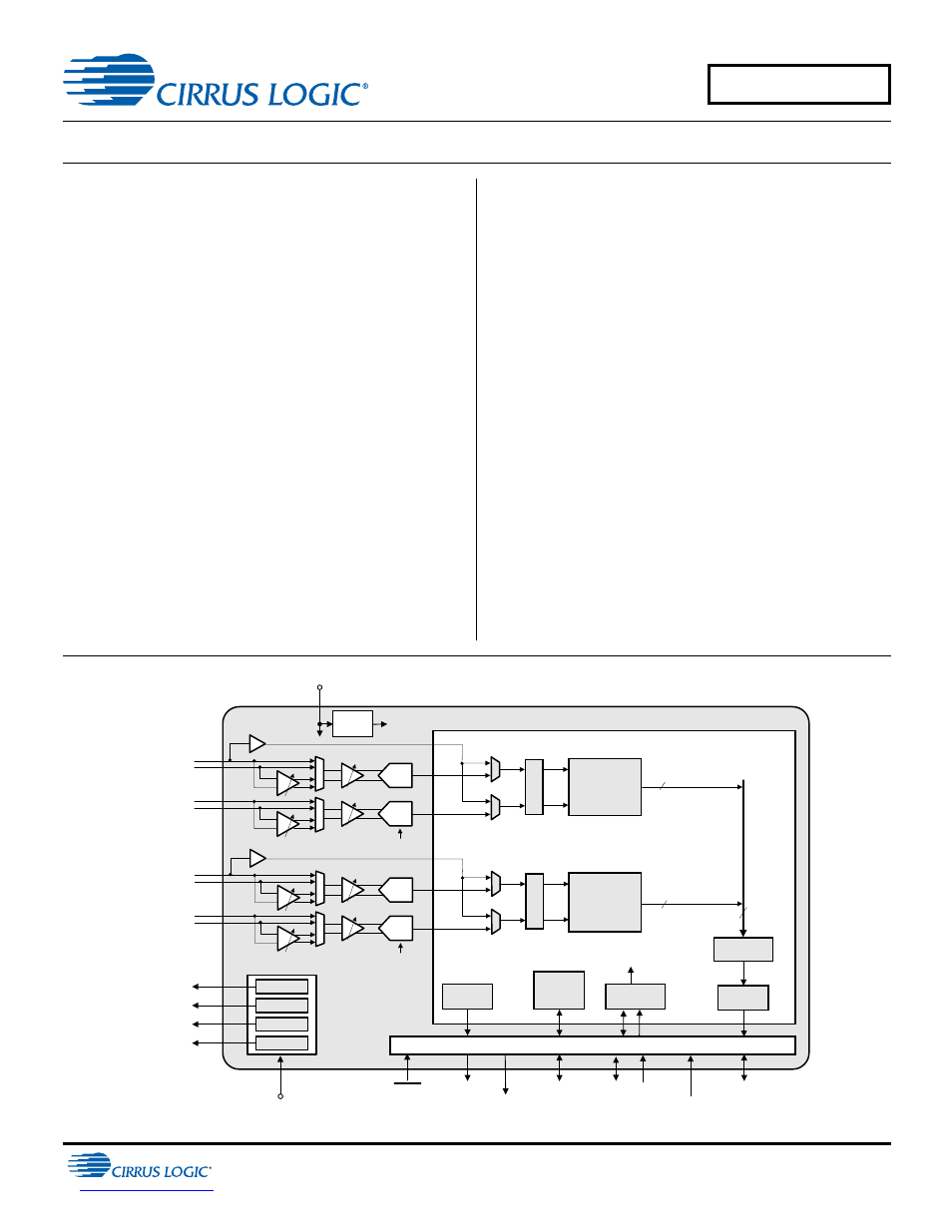
Low-Power Quad-Channel Microphone ADC with TDM Output
Analog Input and ADC Features
91-dB dynamic range (A-weighted) @ 0-dB gain
–84-dB THD+N @ 0-dB gain
Four fully differential inputs: Four analog mic/line inputs
Four analog programmable gain amplifiers
–6 to +12 dB, in 0.5-dB steps
+10 or +20 dB boost for mic input
Four mic bias generators
MUTE pin for quick mic mute and programmable quick
power down
Digital Processing Features
Volume control, mute, programmable high-pass filter,
noise gate
Two digital mic (DMIC) interfaces
Digital Output Features
Two DMIC SCLK generators
Four-channel I
2
S output or TDM output. Four CS53L30s
can be used to output 16 channels of 24-bit 16-kHz
sample rate data on a single TDM line.
System Features
Native (no PLL required) support for 6-/12-MHz, 6.144-/
12.288-MHz, 5.6448-/11.2896-MHz, or 19.2-MHz master
clock rates and 8- to 48-kHz audio sample rates
Master or Slave Mode. Clock dividers can be used to
generate common audio clocks from single-master clock
input.
Low power consumption
Less than 4.5-mW stereo (16 kHz) analog mic record
Less than 2.5-mW mono (8 kHz) analog mic record
Selectable mic bias and digital interface logic voltages
High-speed (400-kHz) I²C™ control port
Available in 30-ball WLCSP and 32-pin QFN
Applications
Voice-recognition systems
Advanced headsets and telephony systems
Voice recorders
Digital cameras and video cameras
CS53L30
Digital Processing
Control
Port
Level Shifters
MIC 1_BIAS
Serial Port
MIC 2_BIAS
VP
MCLK
DMIC1_SCLK
MIC3_BIAS
MIC4_BIAS
–6 to +12 dB,
0.5 dB steps
+10 or +20 dB
ADC1B
–
+
–
+
De
ci
ma
to
rs
MIC1 Bias
MIC2 Bias
MIC3 Bias
MIC4 Bias
HPF, Noise
Gate, Volume,
Mute
Audio
Serial Port
Control Port
RESET
MCLK_INT
Clock Divider
Synchronizer
DMIC
ADC1A
–
+
LDO
VA
VD
2
2
4
MCLK_INT
HPF, Noise
Gate, Volume,
Mute
SYNC
MUTE
Synchronous
SRC
IN1+/DMIC1_SD
IN2–
IN1–
IN2+
DMIC2_SCLK
–
+
–6 to +12 dB,
0.5 dB steps
+10 or +20 dB
ADC2B
–
+
–
+
De
cima
to
rs
ADC2A
–
+
MCLK_INT
IN3+/DMIC2_SD
IN4–
IN3–
IN4+
–
+
CS53L30
DS992F1
MAY '13
Document Outline
- Low-Power Quad-Channel Microphone ADC with TDM Output
- 1 Pin Descriptions
- 2 Typical Connection Diagram
- 3 Characteristics and Specifications
- Table 3-1. Recommended Operating Conditions
- Table 3-2. Absolute Maximum Ratings
- Table 3-3. Combined ADC On-Chip Analog, Digital Filter, SRC, and DMIC Characteristics
- Table 3-4. ADC High-Pass Filter (HPF) Characteristics
- Table 3-5. Analog-Input-to-Serial-Port Characteristics
- Table 3-6. MIC BIAS Characteristics
- Table 3-7. Power-Supply Rejection Ratio (PSRR) Characteristics
- Table 3-8. Power Consumption
- Table 3-10. Switching Specifications—Digital Mic Interface
- Table 3-11. Specifications—I2S
- Table 3-12. Switching Specifications—Time-Division Multiplexed (TDM) Mode
- Table 3-13. Switching Specifications—I2C Control Port
- Table 3-14. Digital Interface Specifications and Characteristics
- Table 3-15. Thermal Overload Detection Characteristics
- 4 Functional Description
- 4.1 Overview
- 4.2 Resets
- 4.3 Interrupts
- 4.4 Capture-Path Inputs
- 4.5 Digital Microphone (DMIC) Interface
- 4.6 Serial Ports
- 4.7 TDM Mode
- 4.8 Synchronous Sample-Rate Converter (SRC)
- 4.9 Multichip Synchronization Protocol
- 4.10 Input Path Source Selection and Powering
- 4.11 Thermal Overload Notification
- 4.12 MUTE Pin
- 4.13 Power-Up and Power-Down Control
- 4.14 I2C Control Port
- 4.15 QFN Thermal Pad
- 5 Systems Applications
- 6 Register Quick Reference
- 7 Register Descriptions
- 7.1 Device ID A and B
- 7.2 Device ID C and D
- 7.3 Device ID E
- 7.4 Revision ID
- 7.5 Power Control
- 7.6 MCLK Control
- 7.7 Internal Sample Rate Control
- 7.8 Mic Bias Control
- 7.9 ASP Configuration Control
- 7.10 ASP Control 1
- 7.11 ASP TDM TX Control 1–4
- 7.12 ASP TDM TX Enable 1–6
- 7.13 ASP Control 2
- 7.14 Soft Ramp Control
- 7.15 LRCK Control 1
- 7.16 LRCK Control 2
- 7.17 MUTE Pin Control 1
- 7.18 MUTE Pin Control 2
- 7.19 Input Bias Control 1
- 7.20 Input Bias Control 2
- 7.21 DMIC1 Stereo Control
- 7.22 DMIC2 Stereo Control
- 7.23 ADC1/DMIC1 Control 1
- 7.24 ADC1/DMIC1 Control 2
- 7.25 ADC1 Control 3
- 7.26 ADC1 Noise Gate Control
- 7.27 ADC1A/1B AFE Control
- 7.28 ADC1A/1B Digital Volume
- 7.29 ADC2/DMIC2 Control 1
- 7.30 ADC2/DMIC2 Control 2
- 7.31 ADC2 Control 3
- 7.32 ADC2 Noise Gate Control
- 7.33 ADC2A/2B AFE Control
- 7.34 ADC2A/2B Digital Volume
- 7.35 Device Interrupt Mask
- 7.36 Device Interrupt Status
- 8 Parameter Definitions
- 9 Plots
- 10 Package Dimensions
- 11 Thermal Characteristics
- 12 Ordering Information
- 13 Revision History