1 octal microphone array to the audio serial port, 1 phase-calibration considerations, Section 5.1 – Cirrus Logic CS53L30 User Manual
Page 38: Cs53l30, Table 5-1. phase mismatch classifications, Rp minimum value is 10 k
38
DS992F1
CS53L30
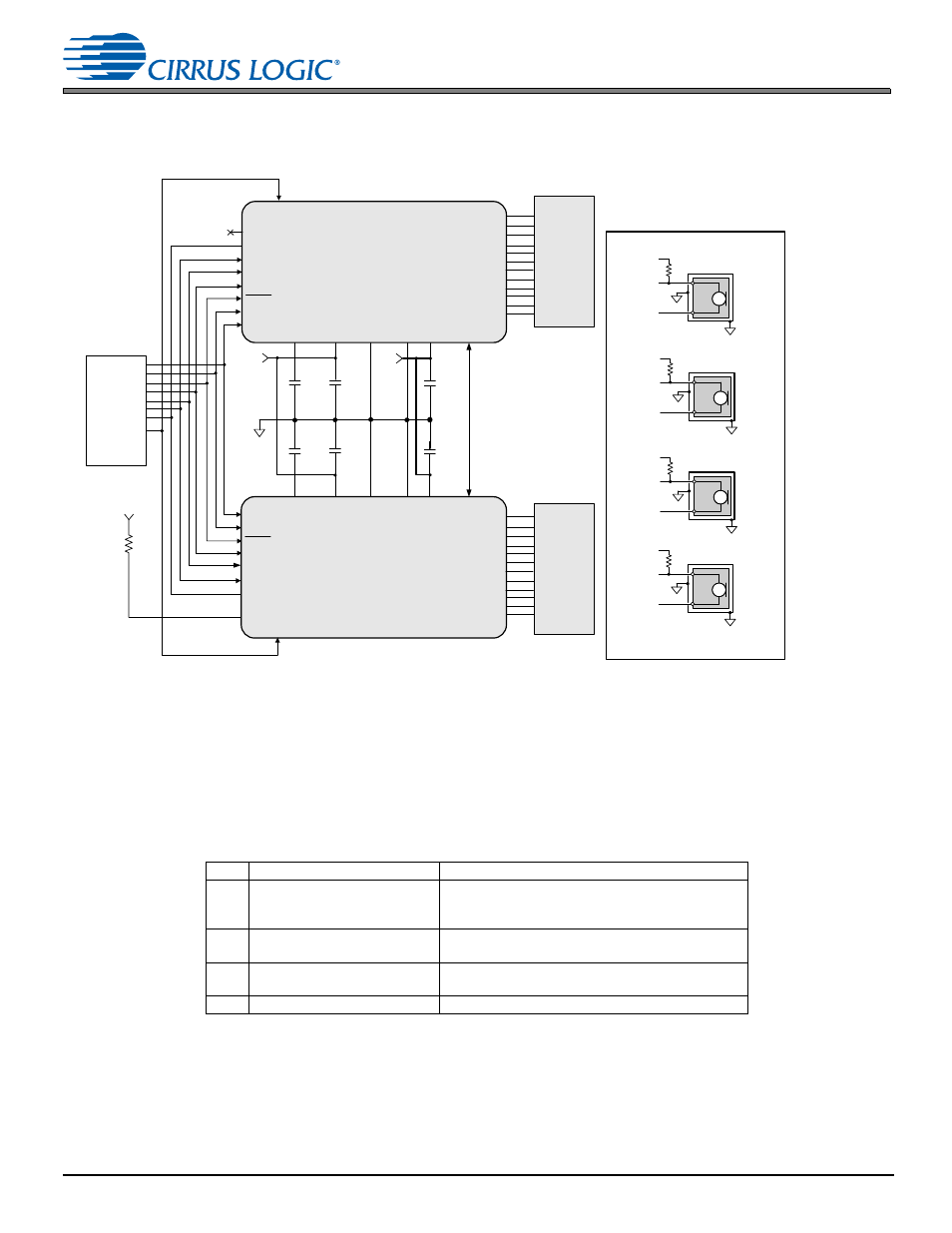
5.1 Octal Microphone Array to the Audio Serial Port
5.1 Octal Microphone Array to the Audio Serial Port
shows connections for an eight-channel mic array to serial port schematic configuration.
Figure 5-1. Octal Microphone Array Dual-CS53L30 Schematic
5.1.1
Phase-Calibration Considerations
The CS53L30 can be used in a multidevice application like the one shown in
. In such a system, there are four
classifications of phase mismatch and they originate from various sources. Each class listed in
may contribute
to the overall phase error.
In this description, it is assumed that board components including the CS53L30 devices have been chosen or fixed. The
system board has been designed, placed, and routed, and thus all systematic phase mismatch due to the fabrication or
manufacturing of the chosen components is called “deterministic.” These systematic elements are time invariant for the
given set of components.
Table 5-1. Phase Mismatch Classifications
Type
Classification
Source
1
Deterministic, time invariant
• Manufacturing tolerances of chosen components
• Board temperature gradients
• Board layout and route
2
Deterministic, time varying
• Power-up sequencing
• LRCK chip-to-chip skew
3
Nondeterministic, time varying
• MCLK, LRCK/FSYNC jitter
• SRC initial conditions
4
Nondeterministic, time invariant • ADC sample aperture
Four-Channel Mic Connection
2.2 µF
*
2.2 µF
*
0.1 µF
*
0.1 µF
*
*
*
0.1 µF
0.1 µF
+1.8 V
+3.6 V
CS53L30
GNDD
GNDA
MIC1_BIAS
IN1+
MIC2_BIAS
MIC3_BIAS
IN4+
SCL
SDA
ASP_LRCK
ASP_SCLK
ASP_SDOUT1
ASP_SDOUT2/AD0
MCLK
VA
VP
MIC4_BIAS
FILT+
CS53L30
GNDD
GNDA
SCL
SDA
ASP_LRCK
ASP_SCLK
ASP_SDOUT1
MCLK
VA
VP
FILT+
Four-Channel
Mic
(see
Connection
Diagram)
Four-Channel
Mic
(see
Connection
Diagram)
SoC
SYNC
SYNC
ASP_SDOUT2/AD0
R
P
+1.8 V
MUTE
RESET
MUTE
RESET
Rbias
Ground Ring
MIC4_BIAS
IN4+
IN4–
Rbias
Ground Ring
MIC1_BIAS
IN1+
IN1–
Rbias
Ground Ring
MIC2_BIAS
IN2+
IN2–
Rbias
Ground Ring
MIC3_BIAS
IN3+
IN3–
IN1–
IN2+
IN2–
IN3+
IN3–
IN4–
MIC1_BIAS
IN1+
MIC2_BIAS
MIC3_BIAS
IN4+
MIC4_BIAS
IN1-
IN2+
IN2-
IN3+
IN3-
IN4-
1. Rp minimum value is 10 k