7 register descriptions, 1 device id a and b, 2 device id c and d – Cirrus Logic CS53L30 User Manual
Page 47: 3 device id e, 4 revision id, 5 power control, Ster descriptions, Pdn_ulp, Bit (see, P. 47
DS992F1
47
CS53L30
7 Register Descriptions
7 Register Descriptions
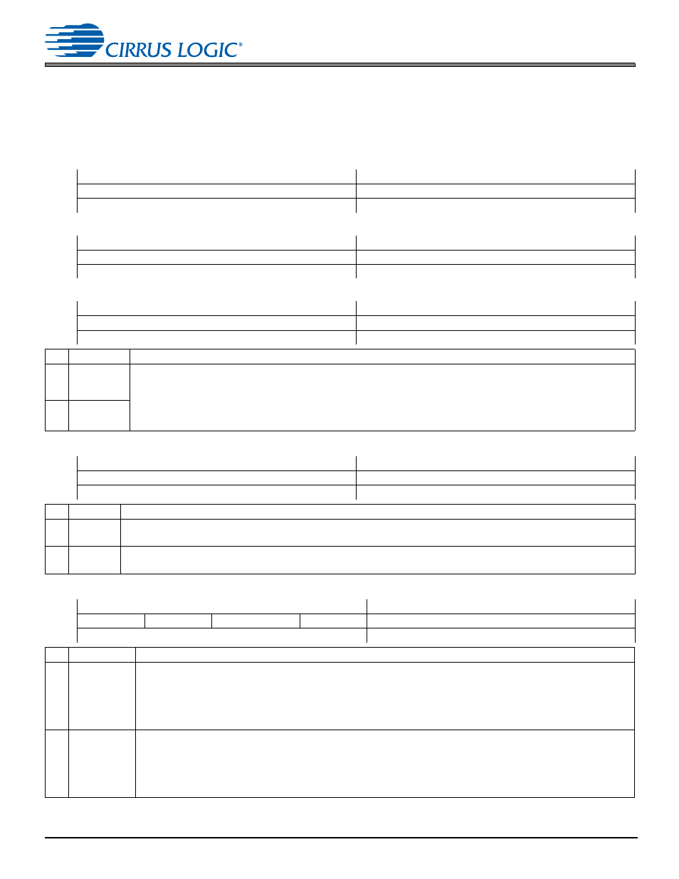
All registers are read/write except for the chip ID, revision register, and status registers, which are read only. Refer to the
following bit definition tables for bit assignment information. The default state of each bit after a power-up sequence or
reset is indicated. All reserved registers must maintain their default state.
7.1 Device ID A and B
Address 0x01
R/O
7
6
5
4
3
2
1
0
DEVIDA[3:0]
DEVIDB[3:0]
Default
0
1
0
1
0
0
1
1
7.2 Device ID C and D
Address 0x02
R/O
7
6
5
4
3
2
1
0
DEVIDC[3:0]
DEVIDD[3:0]
Default
1
0
1
0
0
0
1
1
7.3 Device
ID
E
Address 0x03
R/O
7
6
5
4
3
2
1
0
DEVIDE[3:0]
—
Default
0
0
0
0
0
0
0
0
Bits
Name
Description
7:4
DEVIDA
DEVIDC
DEVIDE
Device ID code for the CS53L30.
DEVIDA 0x5
DEVIDB 0x3
DEVIDC 0xA Represents the “L” in CS53L30
.
DEVIDD 0x3
DEVIDE 0x0
3:0
DEVIDB
DEVIDD
7.4 Revision
ID
Address 0x05
R/O
7
6
5
4
3
2
1
0
AREVID[3:0]
MTLREVID[3:0]
Default
x
x
x
x
x
x
x
x
Bits
Name
Description
7:4
AREVID
Alpha revision. CS53L30 alpha revision level. AREVID and MTLREVID form the complete device revision ID (e.g., A0, B2).
0xA A… 0xF F
3:0 MTLREVID Metal revision. CS53L30 metal revision level. AREVID and MTLREVID form the complete device revision ID (e.g., A0, B2).
0x0 0… 0xF F
7.5 Power
Control
Address 0x06
R/W
7
6
5
4
3
2
1
0
PDN_ULP
PDN_LP
DISCHARGE_FILT+
THMS_PDN
—
Default
0
0
0
1
0
0
0
0
Bits
Name
Description
7
PDN_ULP
CS53L30 power down. Configures the power state of the entire device. After power-up (PDN_ULP: 1
0), subblocks
stop ignoring their individual power controls and are powered according to their settings. PDN_ULP has precedence over
PDN_LP (i.e., if PDN_ULP is set, the ADC and references are all powered down).
0 (Default) Powered up, as per the individual x_PDN controls.
1 Powered down. After PDN_ULP is set and the entire device is powered down, PDN_DONE is set, indicating that
MCLK can be removed.
6
PDN_LP
Partial CS53L30 power down. Configures the power state of the device, with the exception of the reference circuits to
allow for faster startup during power cycles. After power up (PDN_LP: 1
0), subblocks stop ignoring their individual
power controls and are powered according to their settings.
0 (Default) Powered up, as per the individual x_PDN controls.
1 Powered down.
Note: If PDN_ULP is set, the value of PDN_LP is ignored.