3 transmitting data, Fig. 4-17, Cs53l30 – Cirrus Logic CS53L30 User Manual
Page 32
32
DS992F1
CS53L30
4.7 TDM Mode
4.7.3
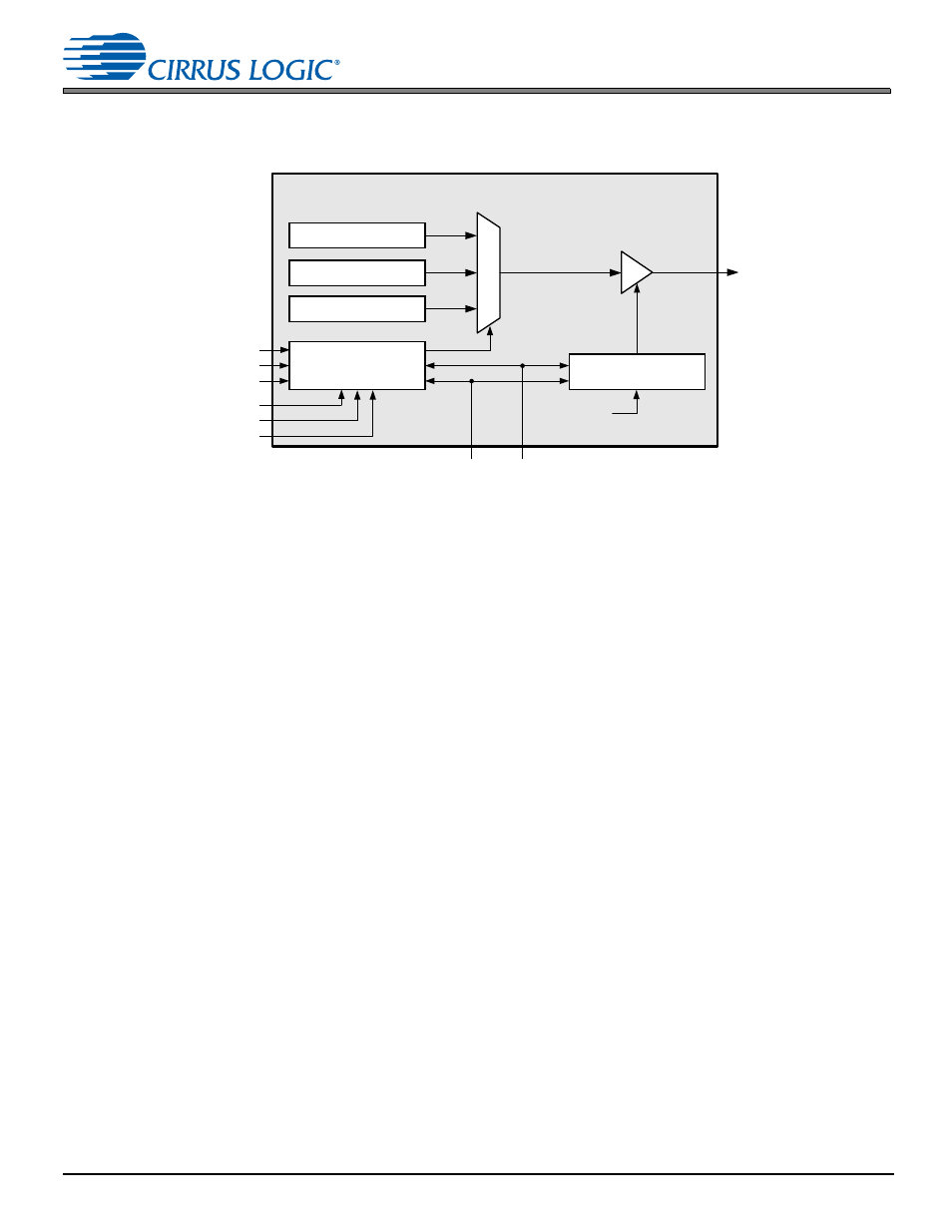
Transmitting Data
shows the TDM transmit subblock.
Figure 4-17. TDM Transmit Subblock Diagram
4.7.3.1 Transmit Data Structuring
Data registers are assigned to slots using the ASP_CHx_LOC, ASP_CHx_TX_STATE, and the ASP_TX_ENABLE
controls. The ASP_CHx_TX_LOC control (“x” is the channel number) determines which of the available 48 slots the data
set should be loaded into, MSB first. If an internal data register is not to be transmitted outside of the part, clear ASP_CHx_
TX_STATE. ASP_TX_ENABLE determines which of the loaded slots are transmitted on the ASP_SDOUT1 pin.
The SDOUT driver enters a Hi-Z state for disabled slots. An important implication of disabling slots is that if a disabled slot
lies between two enabled slots, the SDOUT driver enters a Hi-Z state during the disabled slot segment, but the data for
both enabled slots is transmitted. For example, if a 24-bit data set is assigned to Slots 0–2, but the TX_ENABLE1 bit is
cleared, the highest 8 bits of data are sent in Slot 0, the SDOUT driver enters a Hi-Z state during Slot 1 (the middle 8 bits
of data are lost), and the lowest 8 bits of data are sent in Slot 2.
If the start slot location of a data set overlaps one or more slots of a previous data set, the new data set has higher priority
(e.g., if the Channel 1 data set starts in Slot 0 and the Channel 2 data set starts in Slot 1, Slot 1 contains Channel 2 data).
If two or more data sets are allocated to use the same slot start location, the lowest numbered channel has the highest
priority (e.g., the Channel 2 data set has higher priority than the Channel 3 and Channel 4 data sets).
4.7.3.2 Transmit Data Register Bit Depths
The bit depths of the internal data registers are 24 bits. The configurability of the CS53L30’s TDM data structure makes it
possible to allocate the data register to a different bit depth on the TDM bus than that of its respective internal data register.
If a data set is allocated fewer bits than its internal data register bit depth, the data is truncated. The transmission of the
slots that would have held the excess data can be disabled.
If the data set is allocated a bit depth larger than the bit depth of its internal data registers, zeros are transmitted in the
lower LSBs after all the data in the data register has been transmitted.
4.7.3.3 TDM Bus Sharing among Multiple Devices
Bus sharing is supported for device transmit. Sharing the bus among multiple devices that are attempting to transmit data
simultaneously is not inherent to the TDM architecture. Since the devices may likely be attempting to drive different data
from one another, this presents an opportunity for bus contention.
To prevent bus contention, the data from internal data registers must be allocated to different slots within the TDM stream
using each device’s ASP_CHx_TX_LOC controls.
TDM Transmit
ASP_SDOUT1
Data Registers
ASP _CH1 Data
ASP _CHx Data
ASP _CH4 Data
TDM Slot Assignment
Control
SCLK
ASP _CH4_TX_LOC
FSYNC
ASP _CHx_TX_LOC
ASP _CH1_TX_LOC
ASP _TX_ENABLE [47 :0 ]
48-bit TDM Slot
Enable Control
ASP_CH4_TX_STATE
ASP _CHx_TX_STATE
ASP_CH1_TX_STATE