8 mic bias control, 9 asp configuration control, 10 asp control 1 – Cirrus Logic CS53L30 User Manual
Page 49: C1_bias_pdn, C2_bias_pdn, C3_bias_pdn, C4_bias_pdn, P_ra, P_sd, P_3st
DS992F1
49
CS53L30
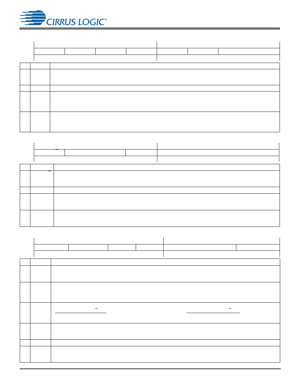
7.8 Mic Bias Control
7.8 Mic
Bias
Control
Address 0x0A
R/W
7
6
5
4
3
2
1
0
MIC4_BIAS_PDN MIC3_BIAS_PDN MIC2_BIAS_PDN MIC1_BIAS_PDN
—
VP_MIN
MIC_BIAS_CTRL[1:0]
Default
1
1
1
1
0
1
0
0
Bits
Name
Description
7, 6,
5, 4
MICx_
BIAS_
PDN
Mic x bias power down
0 Mic x bias driver is powered up and its drive value is set by MIC_BIAS_CTRL.
1 (Default) Mic x bias driver is powered down and the driver is Hi-Z.
3
—
Reserved
2
VP_MIN VP supply minimum voltage setting. Configures the internal circuitry to accept the VP supply with the specified minimum value.
These settings also affect PSRR; see
0 3.0 V. Optimizes VP PSRR performance if the minimum VP supply is expected to fall below 3.2 V.
1 (Default) 3.2 V. Optimizes VP PSRR if VP is at least 3.2 V.
1:0
MIC_
BIAS_
CTRL
MICx bias output voltage control. Sets nominal MICx_BIAS output voltage.
lists actual voltages. To avoid long
ramp-up times between 1.8- and 2.7-V settings, change to the Hi-Z setting before the final setting.
00 (Default) Hi-Z
01 1.80 V
10 2.75 V
11 Reserved
7.9 ASP Configuration Control
Address 0x0C
R/W
7
6
5
4
3
2
1
0
ASP_M/S
ASP_SCLK_INV
ASP_RATE[3:0]
Default
0
0
0
0
1
1
0
0
Bits
Name
Description
7
ASP_M/S ASP Master/Slave Mode. Configures the clock source (direction) for both ASPs.
0 (Default) Slave (input)
1 Master (output). When enabling Master Mode, ASP_RATE must be set to a valid setting defined in
6:5
—
Reserved
4
ASP_
SCLK_INV
ASP_SCLK polarity. Configures the polarity of the ASP_SCLK signal.
0 (Default) Not inverted
1 Inverted
3:0 ASP_RATE ASP clock control dividers. Together with the INTERNAL_FS_RATIO bit, provides divide ratios for ASP clock timings.
lists settings.
1100 (Default) 48 kHz
7.10 ASP Control 1
Address 0x0D
R/W
7
6
5
4
3
2
1
0
ASP_TDM_PDN ASP_SDOUT1_PDN
ASP_3ST
SHIFT_LEFT
—
ASP_SDOUT1_DRIVE
Default
1
0
0
0
0
0
0
0
Bits
Name
Description
7
ASP_
TDM_
PDN
ASP TDM Mode power down. Configures the power state of TDM Mode.
0 TDM Mode
1 (Default) I
2
S Mode
6
ASP_
SDOUT1_
PDN
ASP_SDOUT1 output path power down. Configures the ASP_SDOUT1 path power state for I
2
S Mode (ASP_TDM_PDN = 1).
0 (Default) Powered up
1 Powered down, ASP_SDOUT1 is Hi-Z. Setting this bit does not tristate the serial port clock. If ASP_TDM_PDN is
cleared, setting this bit does not affect ASP_SDOUT1.
5
ASP_3ST ASP output path tristate. Determines the state of the ASP drivers.
Slave Mode (ASP_M/S = 0)
0 (Default) Serial port clocks are inputs and ASP_SDOUTx is output
1 Serial port clocks are inputs and ASP_SDOUTx is Hi-Z
Master Mode (ASP_M/S = 1)
Serial port clocks and ASP_SDOUTx are outputs
Serial port clocks and ASP_SDOUTx are Hi-Z
4
SHIFT_
LEFT
TDM first bit of frame shift 1/2 SCLK left. Configures the start offset of data after rising edge of FSYNC.
0 (Default) No Shift. Data output on second rising edge of SCLK after rising edge of FSYNC (see
).
1 1/2 SCLK shift left. Data output 1/2 SCLK cycle earlier (see
).
3:1
—
Reserved
0
ASP_
SDOUT1_
DRIVE
ASP_SDOUT1 output drive strength.
describes drive-strength specifications.
0 (Default) Normal
1 Decreased