Fig. 4-6, Cs53l30, 4 capture-path inputs – Cirrus Logic CS53L30 User Manual
Page 22
22
DS992F1
CS53L30
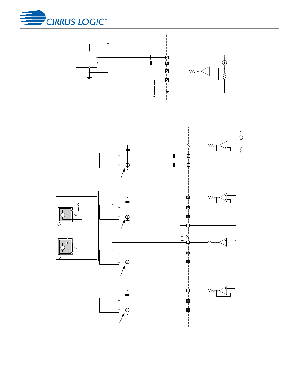
4.4 Capture-Path Inputs
Figure 4-6. Fully Differential Mic Input Connections Example
shows the IN1–IN4 interfaces and the related pseudodifferential connections recommended to achieve the best
common-mode rejection for single-ended internal mics.
Figure 4-7. Pseudodifferential Mic Input Connections Example
Board
Chip
MIC_BIAS_FILT
VP
IN1–
MIC1_BIAS
IN1+
CINM
CINM
Analog
Differential
Microphone
1.0 µF
4.7 µF
GNDA
n
Board
Chip
GNDA
MIC_BIAS_FILT
VP
IN1+
IN1–
MIC1_BIAS
CINM
CINM
1.0 µF
4.7 µF
CINM
CINM
1.0 µF
CINM
CINM
1.0 µF
CINM
CINM
1.0 µF
IN2+
IN2–
MIC2_BIAS
IN3+
IN3–
MIC3_BIAS
IN4+
IN4–
MIC4_BIAS
Board ground connection made
local to the microphone cartridge.
Board ground connection made
local to the microphone cartridge.
Board ground connection made
local to the microphone cartridge.
Board ground connection made
local to the microphone cartridge.
Analog
Microphone
(see
connection
diagram)
Analog
Microphone
(see
connection
diagram)
Analog
Microphone
(see
connection
diagram)
Analog
Microphone
(see
connection
diagram)
Analog Microphone Connection
Two-wire microphone connection
Rbias
Ground Ring
MICx_BIAS
INx+
INx–
Three-wire microphone connection
Ground Ring
MICx_BIAS
INx+
INx–