26 adc1 noise gate control, 27 adc1a/1b afe control, 28 adc1a/1b digital volume – Cirrus Logic CS53L30 User Manual
Page 54: A_pr, Mp[1, A_pga, B_pr, B_pga, Adc1x_vol, Adc1x_pga_vol
54
DS992F1
CS53L30
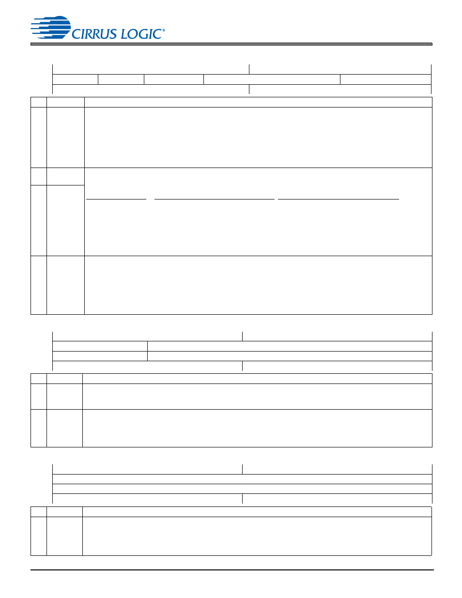
7.26 ADC1 Noise Gate Control
7.26 ADC1 Noise Gate Control
Address 0x28
R/W
7
6
5
4
3
2
1
0
ADC1B_NG
ADC1A_NG
ADC1_NG_BOOST
ADC1_NG_THRESH[2:0]
ADC1_NG_DELAY[1:0]
Default
0
0
0
0
0
0
0
0
Bits
Name
Description
7,6 ADC1x_NG ADC1 noise gate enable for Channels A and B. Enables independent noise gating for Channels A and B if ADC1_NG_
ALL = 0. This bit has no effect if ADC1_NG_ALL = 1
0 (Default) Disable noise gating on Channel x
1 Enable noise gating on Channel x. If a channel’s signal amplitude remains below the threshold setting (refer to ADC1_
NG_THRESH) for longer than the attack delay (debounce) time (refer to ADC1_NG_DELAY), noise gate muting is
applied to only that channel.
• Noise gate muting is removed (released) without debouncing when the signal level exceeds the threshold.
• Noise gate attack and release rates (soft-ramped as a function of Fs or abrupt) are set according to
.
5
ADC1_NG_
BOOST
ADC1 noise gate threshold and boost for Channels A and B. These fields define the signal level where the noise gate begins
to engage. For low settings, the noise gate may not fully engage until the signal level is a few dB lower. Sets threshold level
(±2 dB) for Channel A and B noise gates. ADC1_NG_BOOST configures a +30-dB boost to the threshold setting.
4:2 ADC1_NG_
THRESH
ADC1_NG_THRESH
000
001
010
011
100
101
110
111
Minimum Setting (ADC1_NG_BOOST = 0)
(Default) –64 dB
–66 dB
–70 dB
–73 dB
–76 dB
–82 dB
Reserved
Reserved
Minimum Setting (ADC1_NG_BOOST = 1)
–34 dB
–36 dB
–40 dB
–43 dB
–46 dB
–52 dB
–58 dB
–64 dB
1:0 ADC1_NG_
DELAY
Noise gate delay timing for ADC1 Channels A and B. Sets the delay (debounce) time before the noise gate mute attacks.
Time base = (6144 x (MCLK
INT
scaling factor))/MCLK
INT
00 (Default) 50 x (time base) ms
01 100 x (time base) ms
10 150 x (time base) ms
11 200 x (time base) ms
MCLK
INT
scaling factor is 1, 2, or 4, depending on Fs
INT
and the
lists supported
configurations and their corresponding MCLK
INT
scaling factors.
For MCLK
INT
= 6.144 MHz and MCLK_INT_SCALE = 0, time base is 1 ms.
7.27 ADC1A/1B AFE Control
Address 0x29–0x2A
R/W
7
6
5
4
3
2
1
0
ADC1A_PREAMP[1:0]
ADC1A_PGA_VOL[5:0]
ADC1B_PREAMP[1:0]
ADC1B_PGA_VOL[5:0]
Default
0
0
0
0
0
0
0
0
Bits
Name
Description
7:6
ADC1x_
PREAMP
ADC1x mic preamp gain. Sets the gain of the mic preamp on Channel x.
00 (Default) 0 dB (preamp bypassed)
01 +10 dB
10 +20 dB
11 Reserved
5:0
ADC1x_
PGA_VOL
ADC1x PGA volume. Sets PGA attenuation/gain. Step size: ~0.5 dB.
01 1111–01 1000 +12 dB …
00 0001 +0.5 dB
00 0000 (Default) 0 dB
11 1111 –0.5 dB …
11 1010 –3.0 dB (target setting for 600-mVrms analog-input amplitude)
…
11 0100–10 0000 –6.0 dB
7.28 ADC1A/1B Digital Volume
Address 0x2B–0x2C
R/W
7
6
5
4
3
2
1
0
ADC1A_VOL[7:0]
ADC1B_VOL[7:0]
Default
0
0
0
0
0
0
0
0
Bits
Name
Description
7:0
ADC1x_
VOL
ADC1x/DMICx digital volume. Sets the ADC1 or DMIC signal volume of on Channel x based on the input source selected
(see
). Step size: 1.0 dB
0111 1111–0000 1100 +12 dB
0000 1011 +11 dB …
0000 0000(Default) 0 dB
1111 1111 –1.0 dB
1111 1110 –2.0 dB …
1010 0000 –96.0 dB
1001 1111–1000 0000 Mute