7 tdm mode, 1 bus format and clocking, Cs53l30 – Cirrus Logic CS53L30 User Manual
Page 29: S format bit depths
DS992F1
29
CS53L30
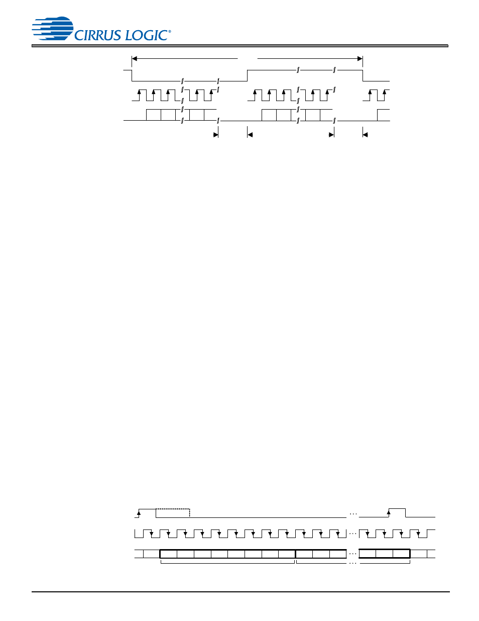
4.7 TDM Mode
Figure 4-11. I
2
S Format
4.6.6.1 I
2
S Format Bit Depths
I
2
S interface data word length (see
) is ambiguous. Fortunately, the I
2
S format is also left justified, with
MSB-to-LSB bit ordering, negating the need for a word-length control register. If at least 24 serial clocks are present per
channel sample, the CS53L30 always sends 24-bit data. If fewer clocks are present, it outputs as many bits as there are
clocks. If more are present, it transmits zeros for any clock cycles after the 24th bit. The receiving device is expected to
load data in MSB-to-LSB order until its word depth is reached, at which point it must discard any remaining LSBs.
4.7 TDM
Mode
The ASP can operate in TDM Mode, which includes the following features:
•
Defeatable SDOUT driver for sharing the TDM bus between multiple devices
•
Flexible data structuring via control port registers
•
Clock master and slave modes
4.7.1
Bus Format and Clocking
The serviceable TDM data stream is defined as 48 8-bit slots, as clocked by SCLK (i.e., ASP_SCLK). Unlike operating the
port in I
2
S Mode, where SCLK is scaled to always be approximately 64 bits per LRCK toggle, SCLK is not required to be
scaled when the device is operating as a clock slave and is not scaled when the device is operating as a clock master. For
example, if a 6.400-MHz clock is used for SCLK, a 16-kHz sample rate would result in 48 available slots or 16 available
24-bit (3-slot) flows with 16 unused SCLK cycles per 400 SCLK cycles (16-kHz frame). If the sample rate were changed
to 8 kHz, the bus would support 48 possible 8-bit slots, but would result in 416 unused SCLK cycles per 800 SCLK cycles
with = 6.400 MHz.
TDM frames are bounded by the FSYNC signal (i.e., ASP_LRCK/FSYNC). The placement of the first bit applied to SDOUT
(i.e., ASP_SDOUT1) in a given TDM frame is programmable using the SHIFT_LEFT bit. By default, the first bit of the TDM
frame is driven on the second rising edge of SCLK following the rising edge of FSYNC. The first bit of the TDM frame can
be moved up a half SCLK cycle earlier by setting the SHIFT_LEFT bit. SHIFT_LEFT and ASP_SCLK_INV can be used in
conjunction to achieve a frame start (i.e., first data bit driven out) on the first rising edge of SCLK as shown in
.
The high time of FSYNC is also programmable by programming
(see
, and
–
show the four possible TDM formats achievable using the ASP_SCLK_INV and SHIFT_LEFT bits. The
number of unused SCLK cycles in each case is zero.
shows an example of the resulting TDM frame structure
when there are unused SCLK cycles in the frame.
Figure 4-12. TDM Format—ASP_SCLK_INV = 0, SHIFT_LEFT = 0
LRCK
SCLK
ASP_SDOUTx
MSB
MSB-1
LSB+1
LSB
1/Fs
ext
Note:
x = 1, 2
MSB
MSB-1
LSB+1
LSB
MSB
SCLK may
stop or
continue
t
extraA
=
None to
some time
SCLK may
stop or
continue
t
extraB
=
None to
some time
Left (A) Channel
Right (B) Channel
0:7
0:6
0:5
0:4
0:3
0:2
0:1
0:0
1:7
1:6
1:5
m:2
m:1
m:0
0:7
FSYNC
SCLK
(ASP_SCLK_INV = 0, default )
SDOUT
(SHIFT_LEFT = 0, default)
Slot 0
Slot 1
m:0
Slot m