4 combined dmic and src response, fsext = fsint, Cs53l30, 4 combined dmic and src response, fs – Cirrus Logic CS53L30 User Manual
Page 61: 1 digital filter response
DS992F1
61
CS53L30
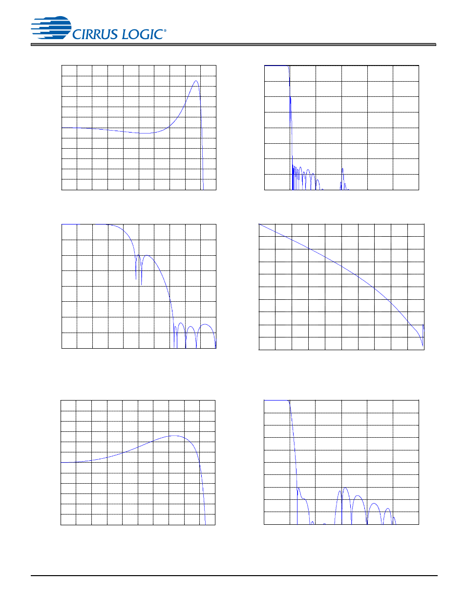
9.1 Digital Filter Response
9.1.4
Combined DMIC and SRC Response, Fs
ext
= Fs
int
Figure 9-15. Passband—ADCx, Notch Disabled
Figure 9-16. Stopband—ADCx, Notch Disabled
Figure 9-17. Transition Band—ADCx, Notch Disabled
Figure 9-18. Phase Response—ADCx, Notch Disabled
Figure 9-19. Passband—DMICx, Notch Disabled
Figure 9-20. Stopband—DMICx, Notch Disabled
0
0.05
0.1
0.15
0.2
0.25
0.3
0.35
0.4
0.45
0.5
-0.25
-0.2
-0.15
-0.1
-0.05
0
0.05
0.1
0.15
0.2
0.25
Frequency (normalized to Fs
ext
)
M
agni
tude (
d
B
)
0
0.5
1
1.5
2
2.5
3
-160
-140
-120
-100
-80
-60
-40
-20
0
Frequency (normalized to Fs
ext
)
M
agni
tude (
d
B
)
0.4
0.42
0.44
0.46
0.48
0.5
0.52
0.54
0.56
0.58
0.6
-160
-140
-120
-100
-80
-60
-40
-20
0
Frequency (normalized to Fs
ext
)
M
agni
tude (
d
B
)
0
0.05
0.1
0.15
0.2
0.25
0.3
0.35
0.4
0.45
0.5
-1000
-900
-800
-700
-600
-500
-400
-300
-200
-100
0
Frequency (normalized to Fs
ext
)
P
has
e (
degr
ees
)
0
0.05
0.1
0.15
0.2
0.25
0.3
0.35
0.4
0.45
0.5
-0.25
-0.2
-0.15
-0.1
-0.05
0
0.05
0.1
0.15
0.2
0.25
Frequency (normalized to Fs)
M
agni
tude (
d
B
)
0
0.5
1
1.5
2
2.5
3
-100
-90
-80
-70
-60
-50
-40
-30
-20
-10
0
Frequency (normalized to Fs)
M
agni
tude (
d
B
)