Figure 21 – Kramer Electronics VS-162V User Manual
Page 53
MENU Commands
49
49
connector (this signal should be properly terminated via the
TERM button
• INT# 1 (internal sync) - switching occurs during the vertical
interval of the video reference signal connected to IN # 1
)
Setting the VS-162V unit as a Large Matrix
UNIT) provides a choice of 4 SWITCHING METHOD settings:
• NoVIS, EXT or INT# 1 (as described above)
• MTX (SYNC from Matrix) - the vertical interval of the video
reference (selected on one unit in the Large Matrix system) is
present on the “SYNC” RS-485 terminal block connector
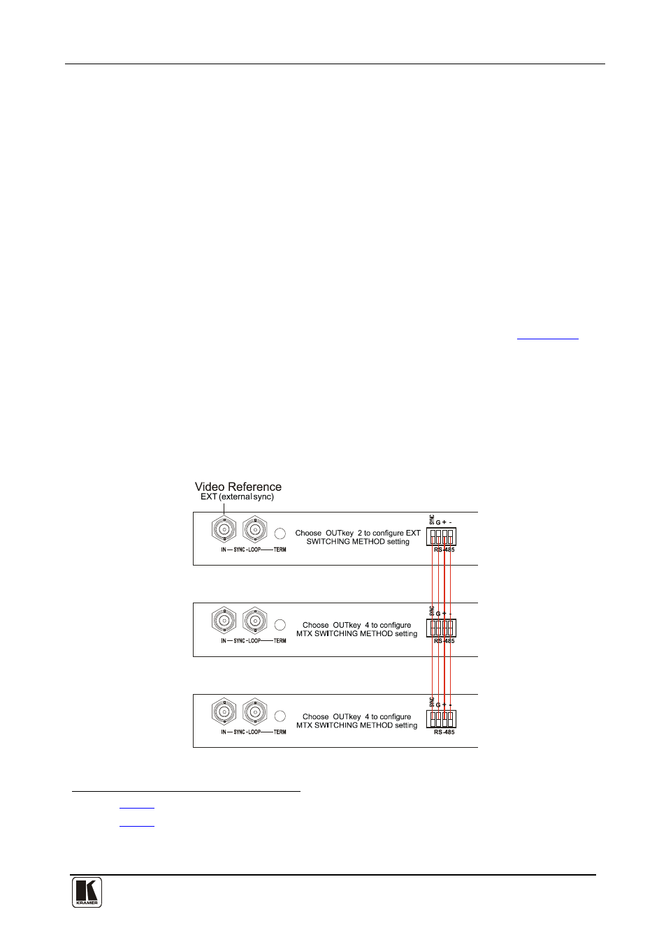
To choose the MTX (SYNC from Matrix) setting
. This
reference signal applies to all switchers in the multi- switcher
system and facilitates switching all VS-162V units simultaneously
• Connect the RS-485 terminal block connectors
• Connect and set the video reference signal on one of the video
units to EXT (external sync) or INT# 1 (internal sync)
between each
switcher in the multi- switcher system
• Set the video reference on the other video units to the MTX
(SYNC from Matrix) setting
Figure 21: Choosing the MTX (SYNC from Matrix) Setting
1 Item 3 in
2 Item 5 in
3 This sets the matrix sync configuration from another (Master) machine
4 Via a straight connection of all 4 PINS