2 setting the machine, 3 setting the machine address, 4 understanding the system mode – Kramer Electronics VS-162V User Manual
Page 25: Setting the machine, Setting the machine address, Understanding the system mode, Table 6: machine # dip-switch settings, Table 6, A multi-channel video switcher application, An expanded matrix switcher application
Understanding Addressing and System Modes
21
21
8.2
Setting the MACHINE #
To control a unit via RS-232 or RS-485, each unit must be identified via its
unique MACHINE #. In an extended matrix configuration, in addition to
the MACHINE #, each unit is identified via its MACHINE ADDRESS #.
Set the MACHINE #
on a VS-162V unit according to
A valid MACHINE # is from 1 to 15. 0 is not a valid address.
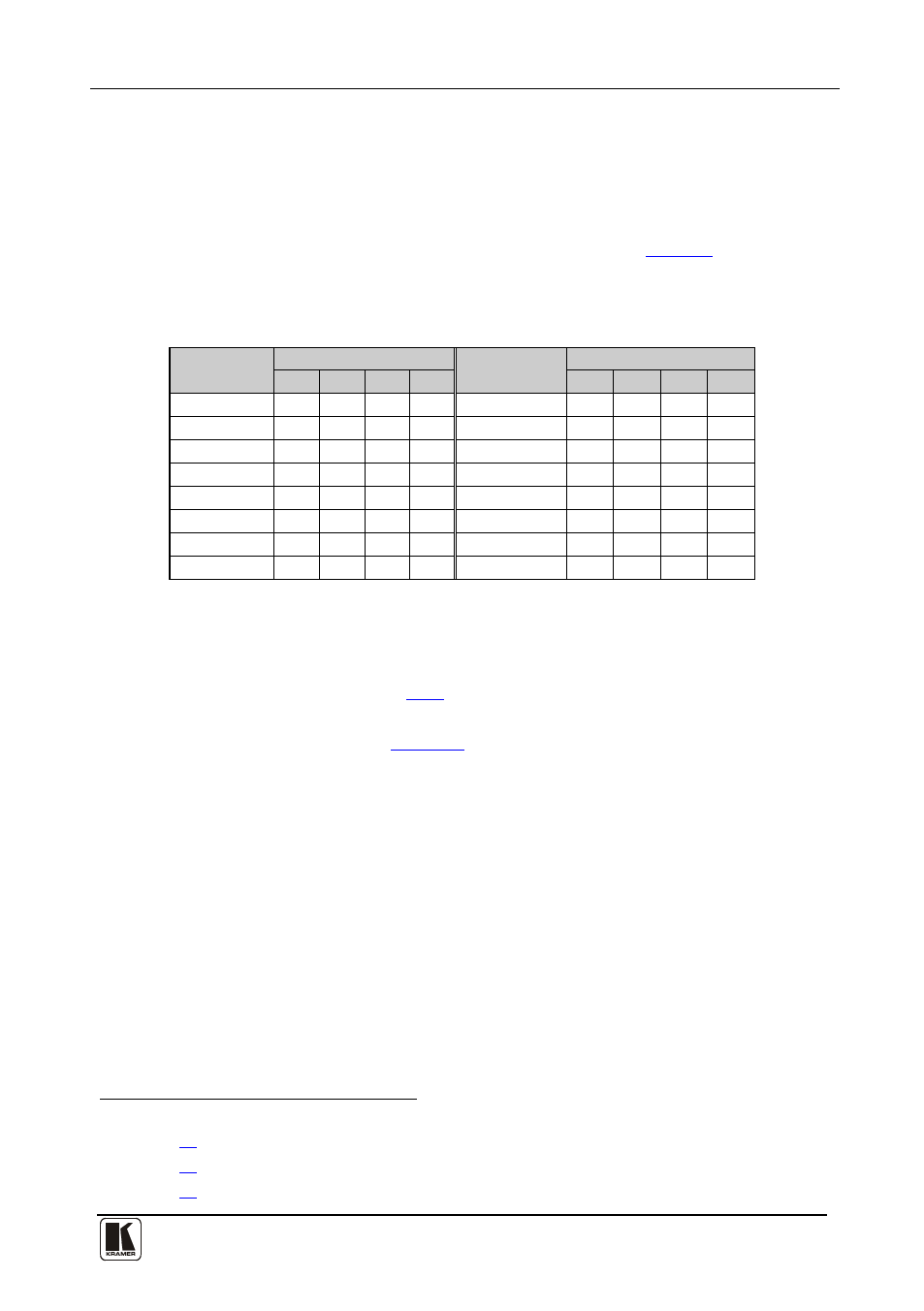
Table 6: Machine # DIP-Switch Settings
MACHINE #
DIP-SWITCH
MACHINE #
DIP-SWITCH
1
2
3
4
1
2
3
4
1
ON
OFF OFF OFF
9
ON
OFF OFF ON
2
OFF ON
OFF OFF
10
OFF ON
OFF ON
3
ON
ON
OFF OFF
11
ON
ON
OFF ON
4
OFF OFF ON
OFF
12
OFF OFF ON
ON
5
ON
OFF ON
OFF
13
ON
OFF ON
ON
6
OFF ON
ON
OFF
14
OFF ON
ON
ON
7
ON
ON
ON
OFF
15
ON
ON
ON
ON
8
OFF OFF OFF ON
8.3
Setting the MACHINE ADDRESS #
The MACHINE ADDRESS # is determined via the MACHINE ADDRESS
Menu command, as section
describes. The MACHINE ADDRESS #
defines which inputs and outputs are configured to that particular unit when
expanding, as the chart in
A valid MACHINE ADDRESS # is from 1 to 36.
8.4
Understanding the SYSTEM Mode
DIP-switch 5 defines whether the VS-162V unit communicates with other
switchers via a common control line.
You can set DIP 5 OFF to disable the Follow-SYSTEM mode in the
following applications:
• Standalone switcher applications
• A multi-channel video switcher application
• An expanded matrix switcher application
1 When using a single unit, set the unit to MACHINE # 1
2 See section
3 See section
4 See section