Table 1, Your video matrix switcher – Kramer Electronics VS-162V User Manual
Page 10
KRAMER: SIMPLE CREATIVE TECHNOLOGY
Your Video Matrix Switcher
6
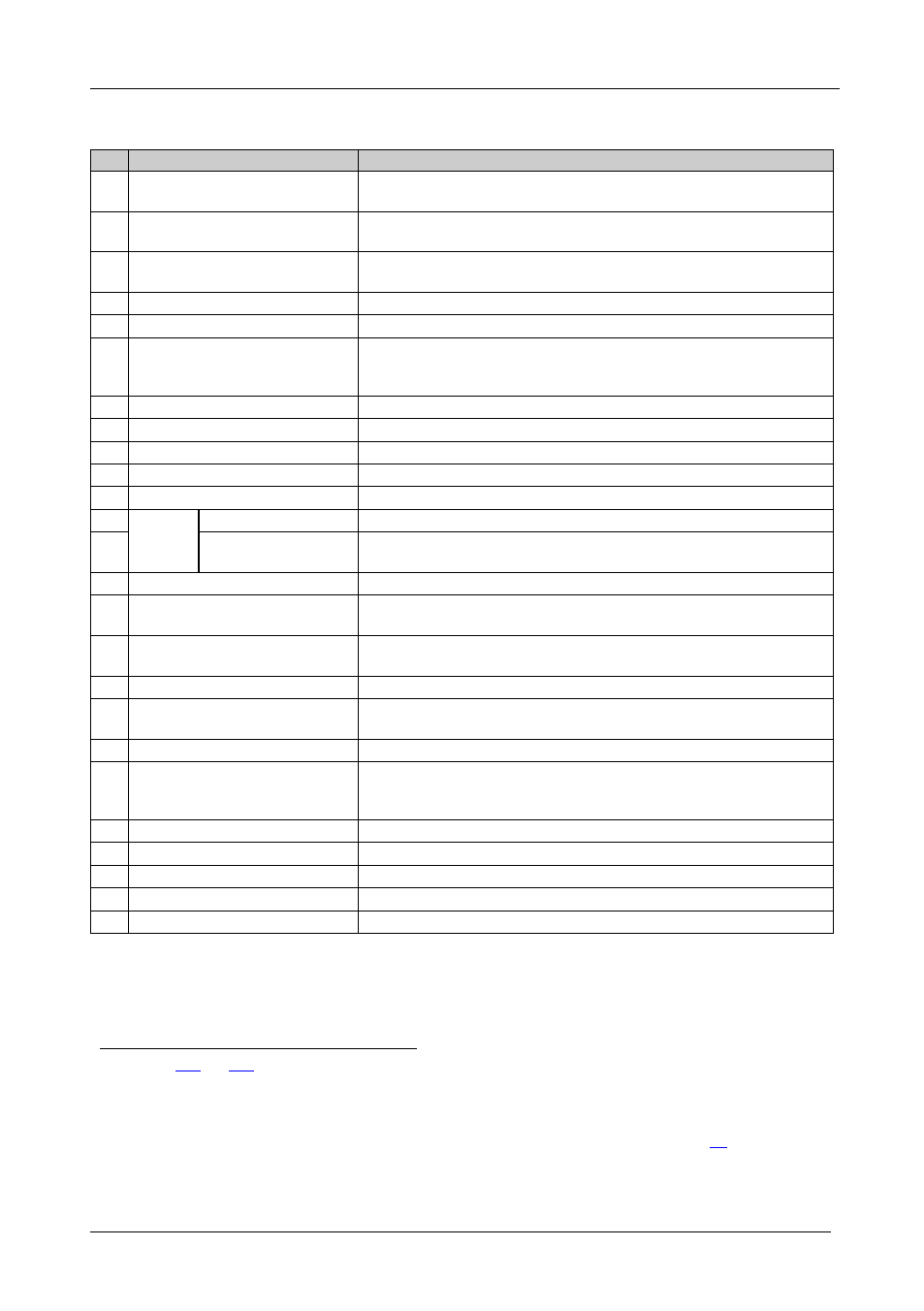
Table 1: Front Panel VS-162V 16x16 Video Matrix Switcher Features
#
Feature
Function
1
IR Receiver
The red LED is illuminated when receiving signals from the Infrared
remote control transmitter
2
ALL Button
Pressing ALL followed by an INPUT button, connects that input to
all outputs
3
OFF Button
An OFF-OUT combination disconnects that output from the inputs; an
OFF-ALL combination disconnects all the outputs
4
STO Button
Stores the current setting in the non-volatile memory
5
RCL Button
Recalls a setup from the non-volatile memory
6
LCD MATRIX display
Displays the selected input(s) switched to the output(s) (above or
below the corresponding OUTPUT label) and user interface
messages
7
LCD STATUS Display
Displays the matrix status
8
OUT Buttons
Select the output to which the input is switched (from 1 to 16)
9
IN Buttons
Select the input to switch to the output (from 1 to 16)
10
MENU Button
Selects the programming commands to setup the switcher
11
TAKE Button
Used to confirm and complete setup and switching
12
SYNC
IN BNC Connector
Connects to the external video sync source
13
LOOP BNC
Connector
Connects to the SYNC IN connector on the next unit
14
TERM SYNC Button
Press to terminate at 75
Ω or release for looping
15
EXT. (extension) KEYS
Terminal Block Connectors
Connects to an external keyboard (remote unit)
16
RS-485 Detachable Terminal
Block Port
Pins # 1 and # 2 are for vertical sync and Ground connection, and
Pins # 3 and # 4 are for RS 485
17
RS-232 IN 9-pin D-sub (F) Port Connects to the PC or the Remote Controller
18
RS-232 OUT 9-pin D-sub (M)
Port
Connects to the RS-232 IN 9-pin D-sub port of the next unit in the
daisy-chain connection
19
SETUP DIP-Switches
DIP-switches for setup of the unit
20
REMOTE IR 3.5mm Mini Jack
Connect to an external IR receiver unit for controlling the machine
via an IR remote controller (instead of using the front panel IR
receiver)
21
Power Switch
Illuminated switch for turning the unit ON or OFF
22
OUT BNC Connectors
Connect to the video acceptors (from 1 to 16)
23
IN BNC Connectors
Connect to the video sources (from 1 to 16)
24
TERM IN Buttons
Press to terminate at 75
Ω or release for looping
25
Power Connector with Fuse
AC connector enabling power supply to the unit
1 In sections
the word “Displays” refers to the LCD MATRIX and STATUS Displays
2 Push in to terminate the sync line. Push out when the sync line extends to another unit
3 If the unit is not the first unit in the line, connects to the RS-232 OUT 9-pin D-sub port of the previous unit in the line
4 Can be used instead of the front panel (built-in) IR receiver to remotely control the machine, see section
5 Push in to terminate the input. Push out when the input extends to another unit (the last unit in the chain must be terminated
when looping)