2 connecting the rs-485 control interface, Connecting the rs-485 control interface, Figure 15: rs-485 connector pinout – Kramer Electronics VS-162V User Manual
Page 30: Refer to section
KRAMER: SIMPLE CREATIVE TECHNOLOGY
Connecting a Control Interface
26
2. Set DIP 7 ON (disabling null-modem adapter use
9.2
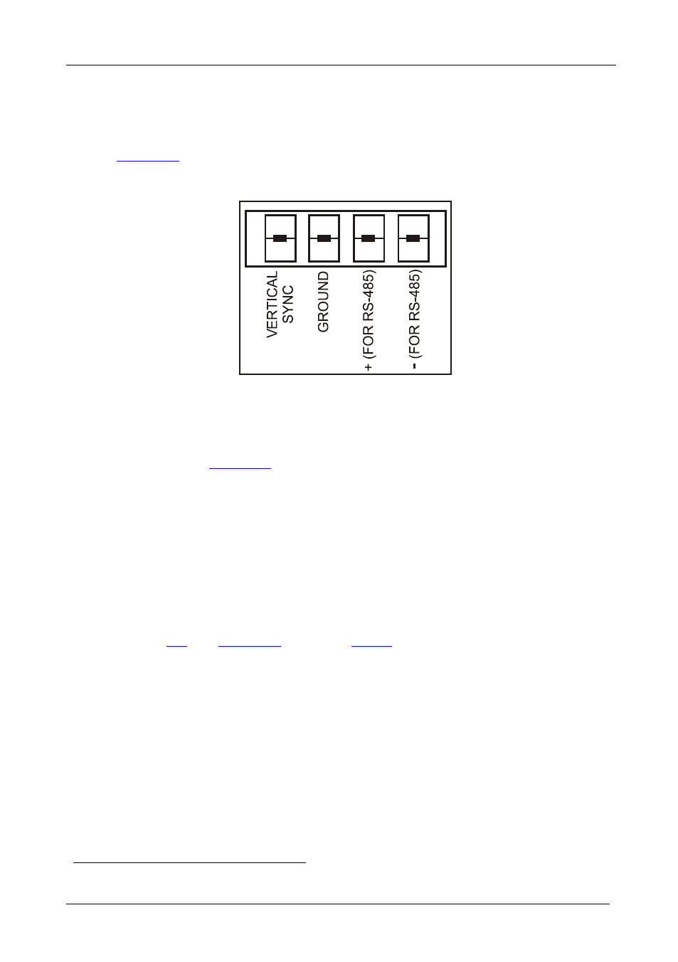
Connecting the RS-485 Control Interface
) on the VS-162V unit.
defines the RS-485 connector pinout for external RS-485 control.
The RS-485 connector is also used (if required) for vertical sync:
Figure 15: RS-485 Connector PINOUT
To connect an RS-485 connector on one VS-162V unit to an RS-485
connector on one or more other switchers (from the series of 16x16 matrix
switchers), as
1. Connect the “+” PIN on the first VS-162V unit to the “+” PIN on the
second VS-162V unit or other unit
2. Connect the “-” PIN on the first VS-162V unit to the “-” PIN on the second
VS-162V unit or other unit
3. If shielded cable is used for an RS-485 connection, connect the shield to the
Ground PIN.
For details about how to configure the vertical sync (if required), refer to
section
1 See section 8