Figure 16 – Kramer Electronics VS-162V User Manual
Page 31
Connecting a Control Interface
27
27
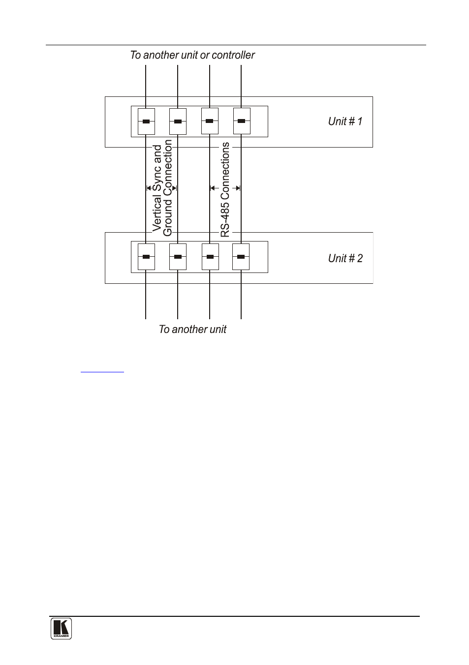
Figure 16: Connecting the RS-485 Connectors between Two VS-162V Units
illustrates the RS-485 line that connects:
• Between each VS-162V unit
• To the PC via a Kramer Tools VP-43xl Interface Converter
(connect the 9-pin D-sub PC COM port to the “RS-232 in” 9-pin
D-sub port on the VP-43xl. Next, connect the RS-485 port on the
VP-43xl to the RS-485 ports on the VS-162V units)
See also other documents in the category Kramer Electronics Routers:
- VM-28H (23 pages)
- VM-216H (25 pages)
- VM-22H (12 pages)
- VM-24H (23 pages)
- VM-24HC (21 pages)
- VM-24HD (10 pages)
- VM-24HDCP (19 pages)
- VM-42 (8 pages)
- VP-222K (10 pages)
- VP-242 (8 pages)
- VP-32K (13 pages)
- VS-202YC (23 pages)
- 4x1S (15 pages)
- 4x1V (12 pages)
- 6241HDxl (10 pages)
- 6241N (10 pages)
- 6502 (12 pages)
- PT-201VGA (8 pages)
- TailorMade (21 pages)
- TailorMade (22 pages)
- VP-1201 (50 pages)
- VP-12x8 (34 pages)
- VP-1608 (46 pages)
- VS-88SDI (42 pages)
- VP-321xl (37 pages)
- VP-16x18AK (60 pages)
- VP-201xl (8 pages)
- VP-211K (15 pages)
- VP-27 (32 pages)
- VS-66HN (25 pages)
- VS-88HDxl (43 pages)
- VP-28 (42 pages)
- VP-2x2 (17 pages)
- VP-31 (25 pages)
- VP-311DVI (20 pages)
- VS-88HD (21 pages)
- VS-88HD (44 pages)
- VP-31KSi (16 pages)
- VP-81KSi (51 pages)
- VP-31KSi (48 pages)
- VP-41 (8 pages)
- VP-411DS (22 pages)
- VS-81HDxl (25 pages)
- VP-4x1CS (39 pages)
- VP-4x4K (61 pages)