7 configuring the vs-162v video matrix switcher, 1 configuring the standalone vs-162v, 1 configuring a 16x16 composite video switcher – Kramer Electronics VS-162V User Manual
Page 14: Configuring the vs-162v video matrix switcher, Configuring the standalone vs-162v, Configuring a 16x16 composite video switcher, 7configuring the vs-162v video matrix switcher
KRAMER: SIMPLE CREATIVE TECHNOLOGY
Configuring the VS-162V Video Matrix Switcher
10
7
Configuring the VS-162V Video Matrix Switcher
Using the VS-162V unit and/or other 16x16 matrix switchers in the series
• A standalone switcher (see section
,
you can assemble the following kinds of systems:
• A multi-channel video switcher (see section
• An expanded matrix switcher (see section
• A system of interconnected switchers (see section
Note: When configuring multiple units, each unit must have an address. For
an explanation on addressing and system modes, see section
7.1
Configuring the Standalone VS-162V
This section describes how to configure your VS-162V as a standalone
switcher for:
• Composite video (CV) (see section
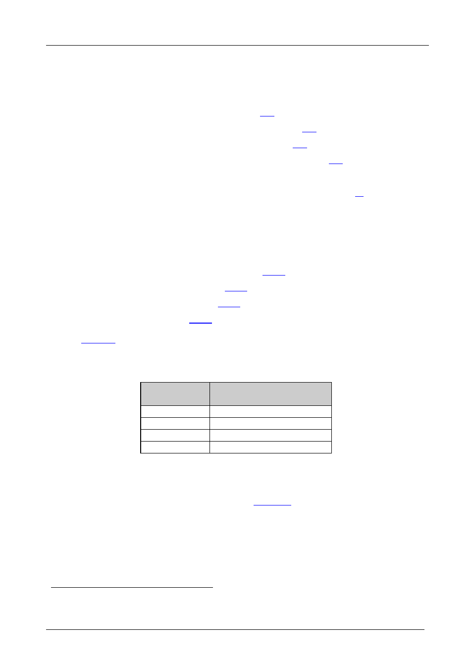
defines the number of inputs and outputs for each signal
configuration:
Table 3: Standalone Switcher Configuration for CV, Y/C, YUV (RGB) and RGBS
Configuration
Number of Inputs and Outputs
on a Standalone Unit
Composite
16x16
s-Video (Y/C)
8x8
YUV / RGB
5x5
RGBS
4x4
7.1.1 Configuring a 16x16 Composite Video Switcher
By default, a single VS-162V unit is configured for composite video with
16 inputs and 16 outputs, as shown in
1 Including the VS-1616A (a 16x16 analog balanced stereo audio matrix switcher), the VS-1616SDI (a 16x16 digital video
matrix switcher), and the VS-1616AD (a 16x16 digital audio matrix switcher)