8 understanding addressing and system modes, 1 setting the dip-switches, Understanding addressing and system modes – Kramer Electronics VS-162V User Manual
Page 24: Setting the dip-switches, Figure 12: rear panel dip-switches, Table 5: dip-switch definitions, 8understanding addressing and system modes
KRAMER: SIMPLE CREATIVE TECHNOLOGY
Understanding Addressing and System Modes
20
8
Understanding Addressing and System Modes
In order to control multiple machines, the VS-162V uses a system of
addressing that includes hardware DIP-switches and menu commands. The
DIP-switches are used to set the MACHINE# and menu commands are used
to set the MACHINE ADDRESS #. Note the following:
• A standalone machine is always set to MACHINE# 1
• When configuring multiple VS-162V units or a matrix of VS-162V
machines, the array is viewed as one large unit and the DIP-switches
of all machines are set to the same MACHINE#. However, each
machine is set to a unique MACHINE ADDRESS # with a menu
command on its display panel according to the addressing rule shown
in
• When configuring a mix of different model machines, each group of
models receives a different MACHINE# and each machine is set to a
unique MACHINE ADDRESS # (see section
8.1
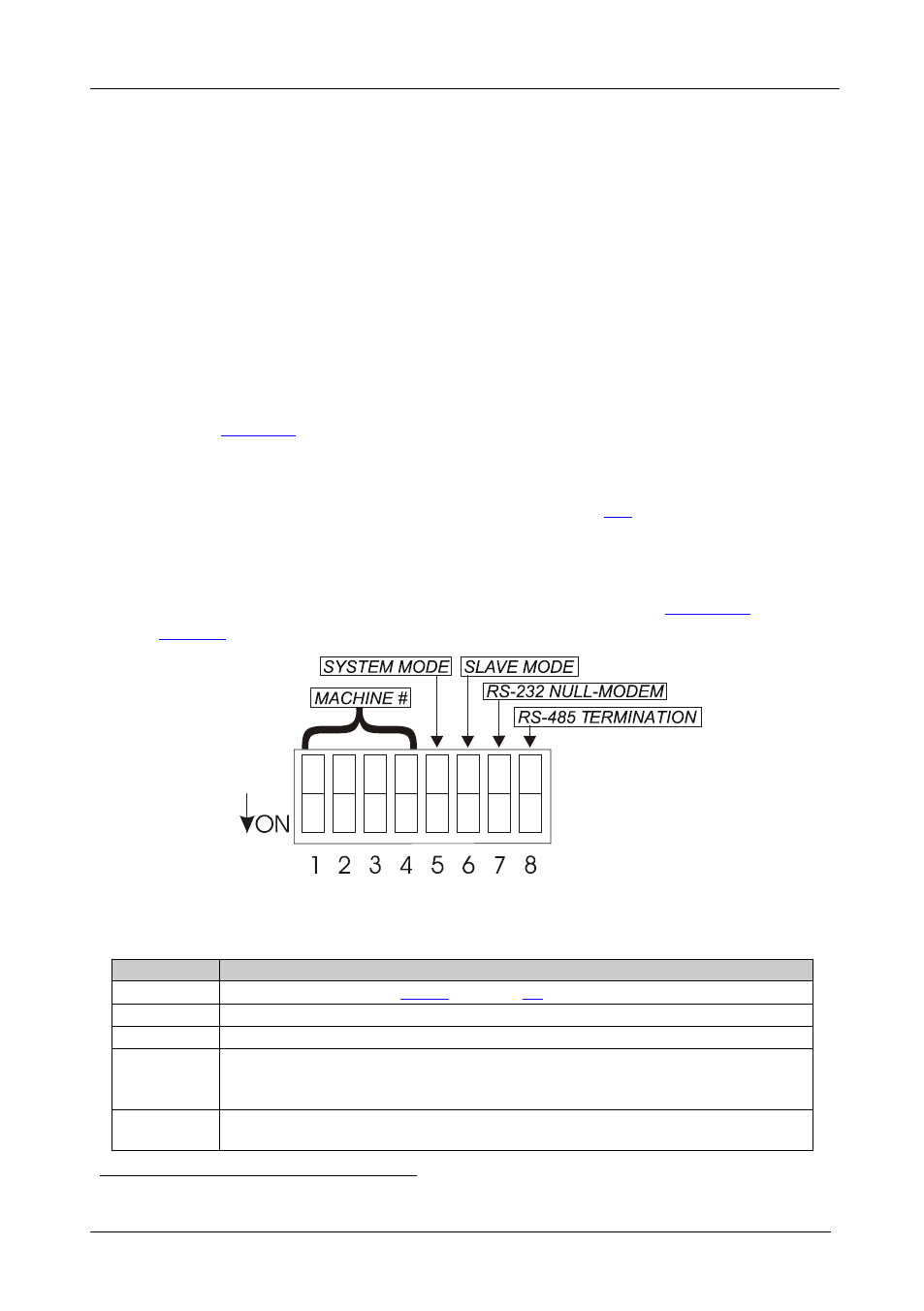
Setting the DIP-Switches
Configure the VS-162V by setting the 8 DIP-switches as
Figure 12: Rear Panel DIP-switches
Table 5: DIP-switch Definitions
DIP-switch #
Function:
1-4
Set the MACHINE # (see
5
Enables (ON) or disables (OFF) the Follow-SYSTEM mode
6
Enables (ON) or disables (OFF) the SLAVE mode in a multi-channel configuration
7
Disables use of a null-modem adapter
OFF = RS-232 connection via a null-modem adapter
ON = RS-232 connection without a null-modem adapter
with RS-232
8
RS-485 termination for first and last machine = ON (RS-485 line terminates with
110
Ω); for others = OFF (RS-485 line is open)